
Anti-syphon emitter

a technology of emitter and emitter body, which is applied in watering devices, horticulture, agriculture, etc., can solve the problems of affecting the quality of water supply,

Inactive Publication Date: 2008-11-04
A I INNOVATIONS
View PDF12 Cites 35 Cited by
  • Summary
  • Abstract
  • Description
  • Claims
  • Application Information

AI Technical Summary

Benefits of technology

The anti-syphon emitter effectively prevents soil ingestion and bacterial growth by slowly releasing air and water, maintaining system functionality and reducing maintenance needs, even in undulating terrain and wastewater applications.

Problems solved by technology

When drip irrigation systems are buried underground, problems can arise when the water pressure is shut off.
This results in a vacuum in the tube, causing soil to be sucked back into another emitter, thereby plugging the second emitter.
However, if the slope is undulating or complex, then the positioning of vacuum relief valves can be both difficult and expensive.
In special conditions, such as on golf courses, especially putting greens, the presence of vacuum relief valves may be unacceptable.
The problem with this type of emitter is that if the water contains any biological matter, bacteria may multiply and form slimes that will block the emitter on the next cycle.

Method used


Image

  • Anti-syphon emitter
  • Anti-syphon emitter
  • Anti-syphon emitter

Examples


example

[0022]An experimental subsurface drip irrigation (SDI) effluent disposal system according to this invention was installed, operated and monitored. The principal purpose of the trial was to quantify the environmental hydraulic performance of a high rate SDI effluent disposal application utilizing tertiary treated municipal effluent to a land disposal site comprising volcanic soils within a forest situation, which involved very severe terrain and a significantly hilly and undulating topography.

[0023]The bulk of the trial utilized standard 16 mm OD 2 L / hr PC Wasteflow, which was laid out conventionally across the contour. (Wasteflow is a product of Geoflow, Inc.) One separate and distinct portion of the project included three buried lines with the anti-syphon drip emitter of this invention (Anti-syphon emitters herein). The emitters / pipe were 18 mm OD 2 L / hr PC and did not include bactericide-lined tube. The Anti-syphon emitters included Rootguard (Rootguard is a product of Geoflow, In...


PUM


Abstract

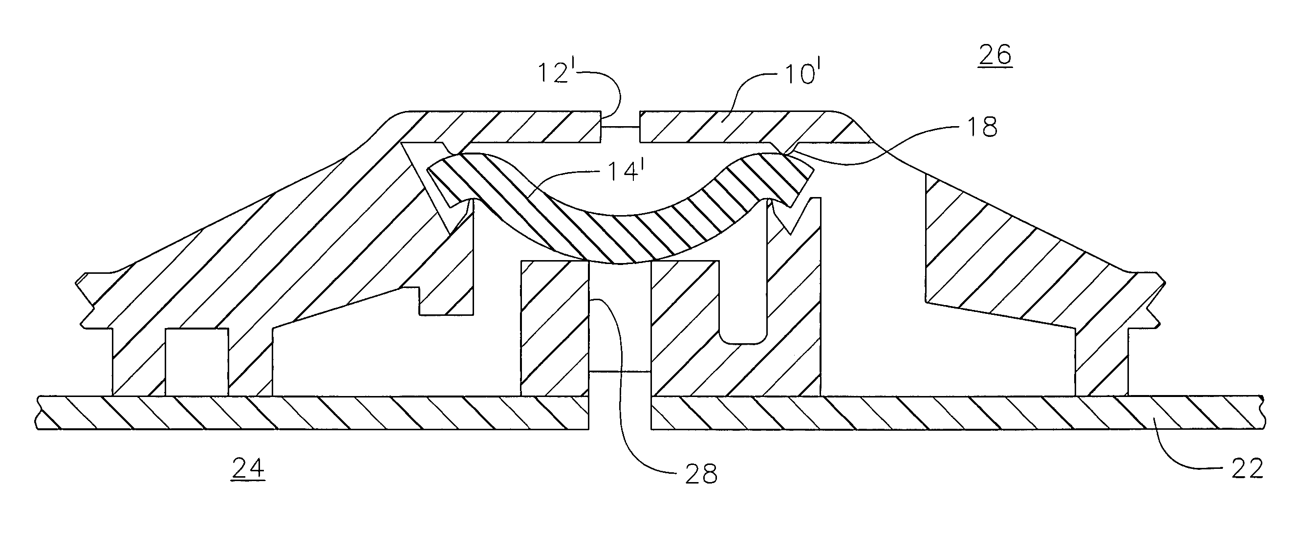
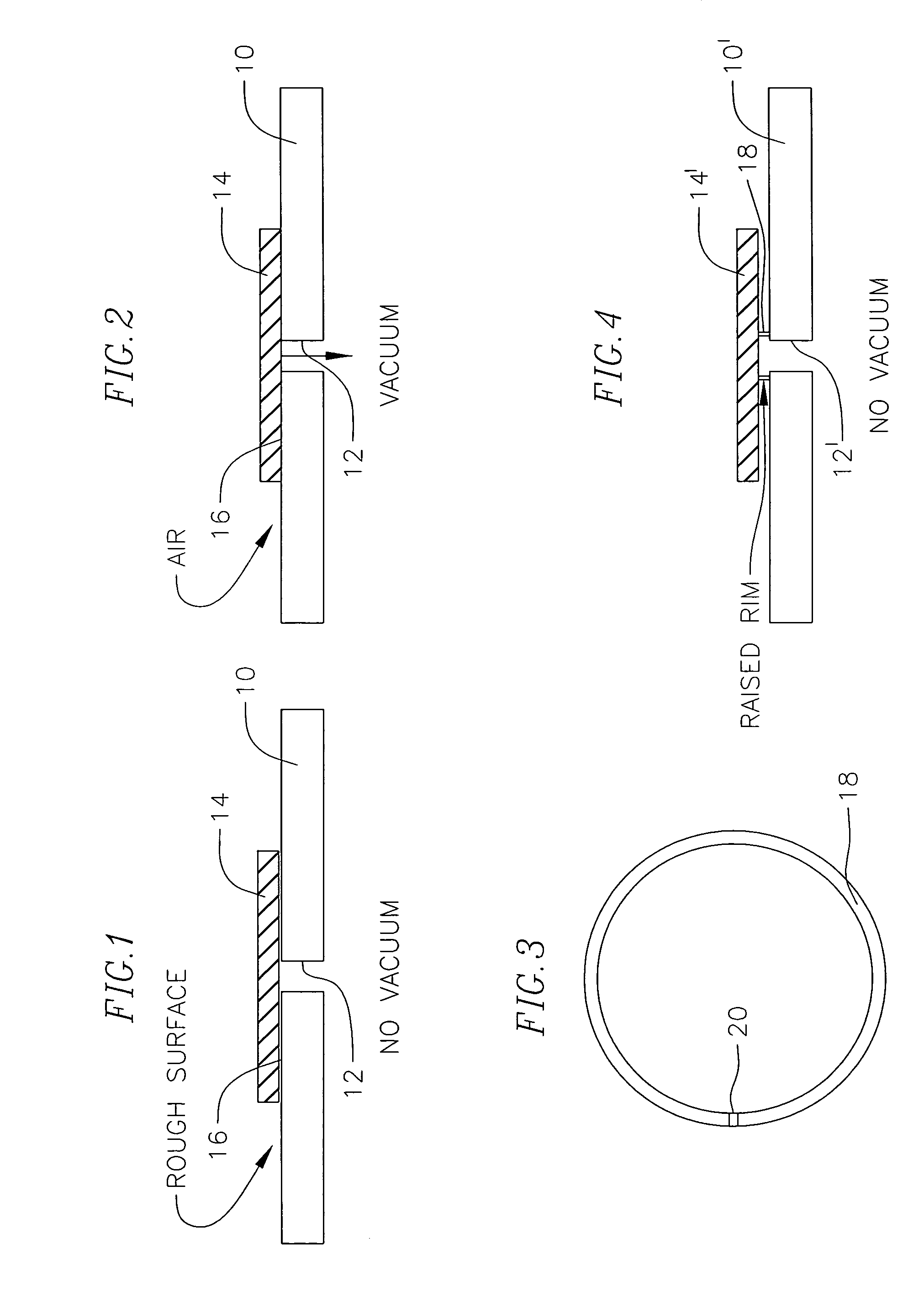
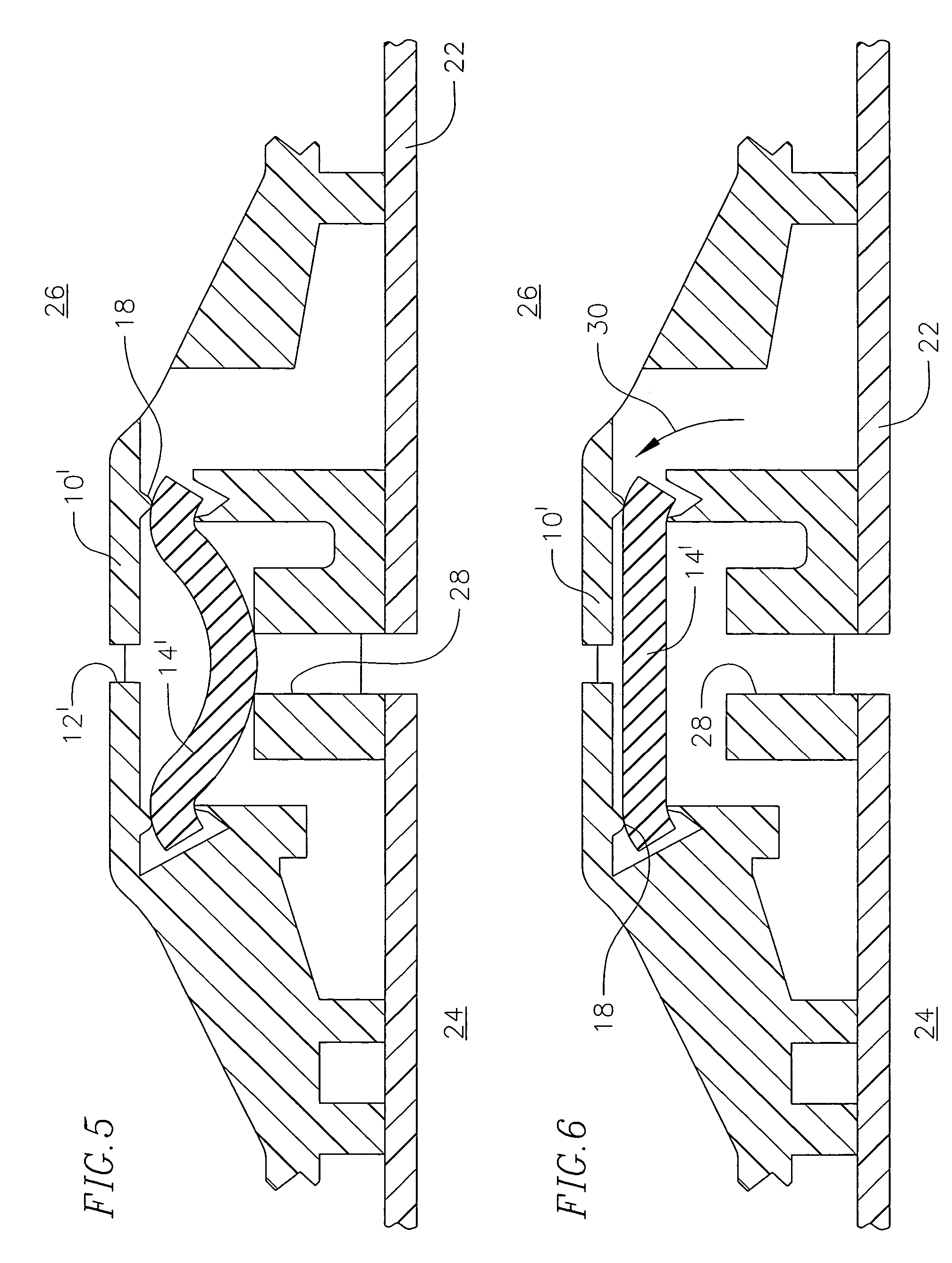
A drip irrigation emitter includes a housing containing an inlet opening for receiving water from a supply tube and an outlet opening for emitting water at a pressureless drip rate. A labyrinth inside the emitter receives water from the supply tube through the inlet opening, reducing its pressure and emitting the water at a drip rate. A flexible pressure-compensating diaphragm inside the housing flexes elastically under pressure changes of water entering in the opening from the supply tube. A raised structured surface positioned between the inlet opening and the diaphragm prevents the diaphragm from sealing off water entry to the emitter housing through the inlet opening when water pressure in the supply tube is shut off. The raised structured surface is configured to allow air contained in the soil to be drawn backwards through the emitter at a very slow rate, thereby inhibiting emitter blockage caused by soil ingestion.

Description

CROSS-REFERENCE[0001]This application claims priority to U.S. Provisional Application 60 / 677,520, filed May 4, 2005, the entire disclosure of which is incorporated herein by this reference.FIELD OF THE INVENTION[0002]This invention relates to drip irrigation emitter units, and more particularly, to an anti-syphon emitter that allows air to be drawn backwards through the emitter at a very slow rate, thereby inhibiting flow of soil or soil and water into the emitter.BACKGROUND[0003]When drip irrigation systems are buried underground, problems can arise when the water pressure is shut off. There are two scenarios: Most drip irrigation emitters will allow the water in the tube to run out into the soil when the water pressure is off. This results in a vacuum in the tube, causing soil to be sucked back into another emitter, thereby plugging the second emitter. To avoid this risk, almost all buried drip systems are fitted with vacuum relief valves. When the slope is monotonic this is a com...

Claims


Application Information

Patent Timeline
Patent Type & Authority Patents(United States)
IPC IPC(8): B05B15/00
CPCA01G25/023Y02A40/22
Inventor RUSKIN, RODNEY
Owner A I INNOVATIONS
Learn More