
Flow-through oxygenator

a flow-through oxygenator and oxygenator technology, applied in the direction of oxidation water/sewage treatment, sustainable biological treatment, seed and root treatment, etc., can solve the problems of adversely affecting life forms, high energy requirements, and many pollutants, and achieve the effect of high energy requirements

Inactive Publication Date: 2006-07-13
OXYGENATOR WATER TECH
View PDF17 Cites 42 Cited by
  • Summary
  • Abstract
  • Description
  • Claims
  • Application Information

AI Technical Summary

Benefits of technology

[0017] This invention includes a method to promote growth and increase yield of plants by application of superoxygenated water. The water treated with the emitter of this invention is one example of superoxygenated water. Plants may be grown in hydroponic culture or in soil. The use of the flow-through model for drip irrigation of crops and for raising the dissolved oxygen content of waste water treatment is disclosed.

Problems solved by technology

For example, fish held in a limited environment such as an aquarium, a bait bucket or a live hold tank may quickly use up the dissolved oxygen in the course of normal respiration and are then subject to hypoxic stress, which can lead to death.
Organic pollutants from agricultural, municipal and industrial facilities spread through the ground and surface water and adversely affect life forms.
Many pollutants are toxic, carcinogenic or mutagenic.
Therefore, the electrodes tend to foul or pit and have a limited life in these corrosive environments.
Pumps to supply oxygen have high power requirements and the noise and bubbling may further stress the animals.
The available electrolytic generators likewise have high power requirements and additionally run at high voltages and produce acidic and basic water which are detrimental to live animals.

Method used


Image

  • Flow-through oxygenator
  • Flow-through oxygenator
  • Flow-through oxygenator

Examples


example 1

Oxygen Emitter

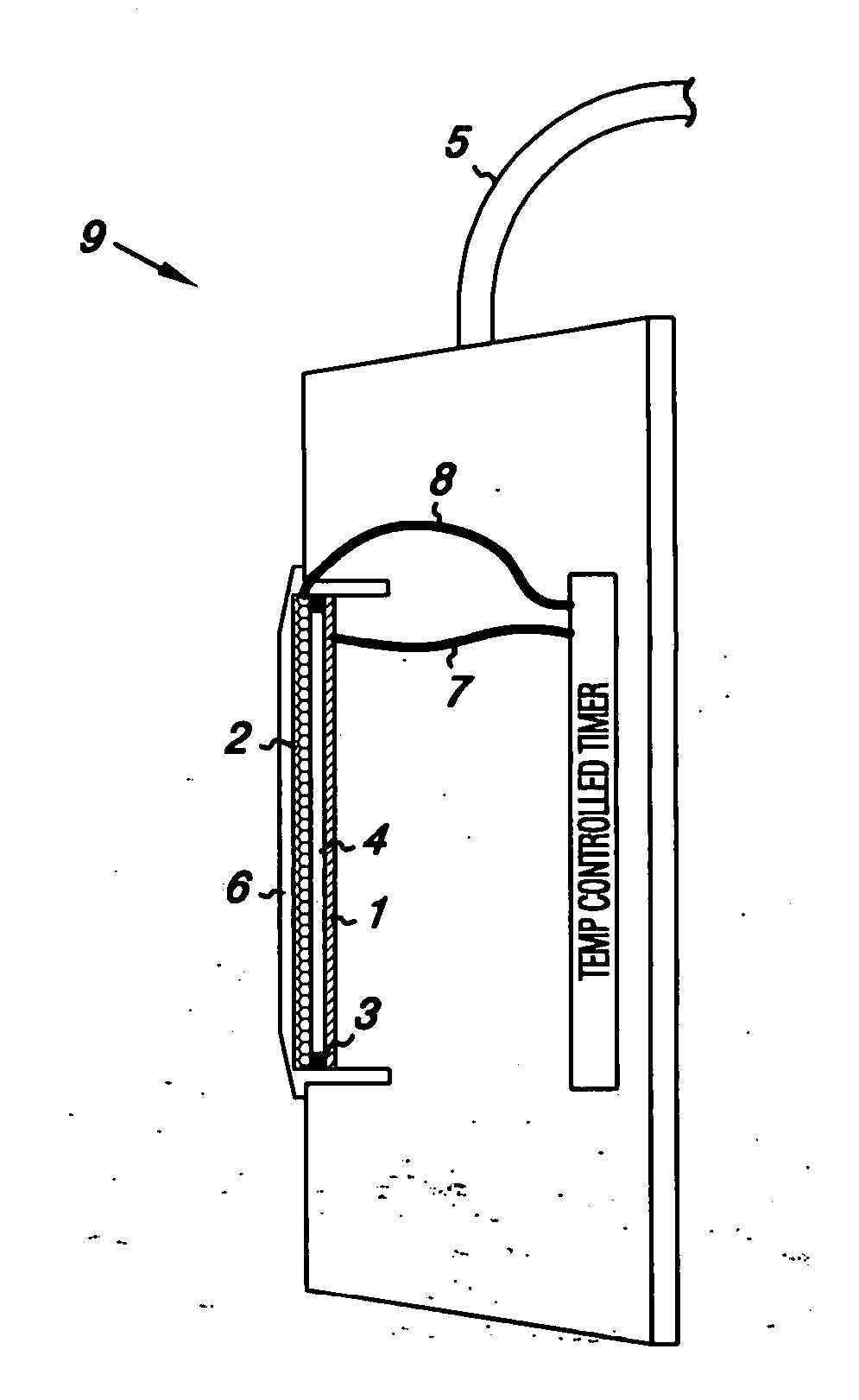
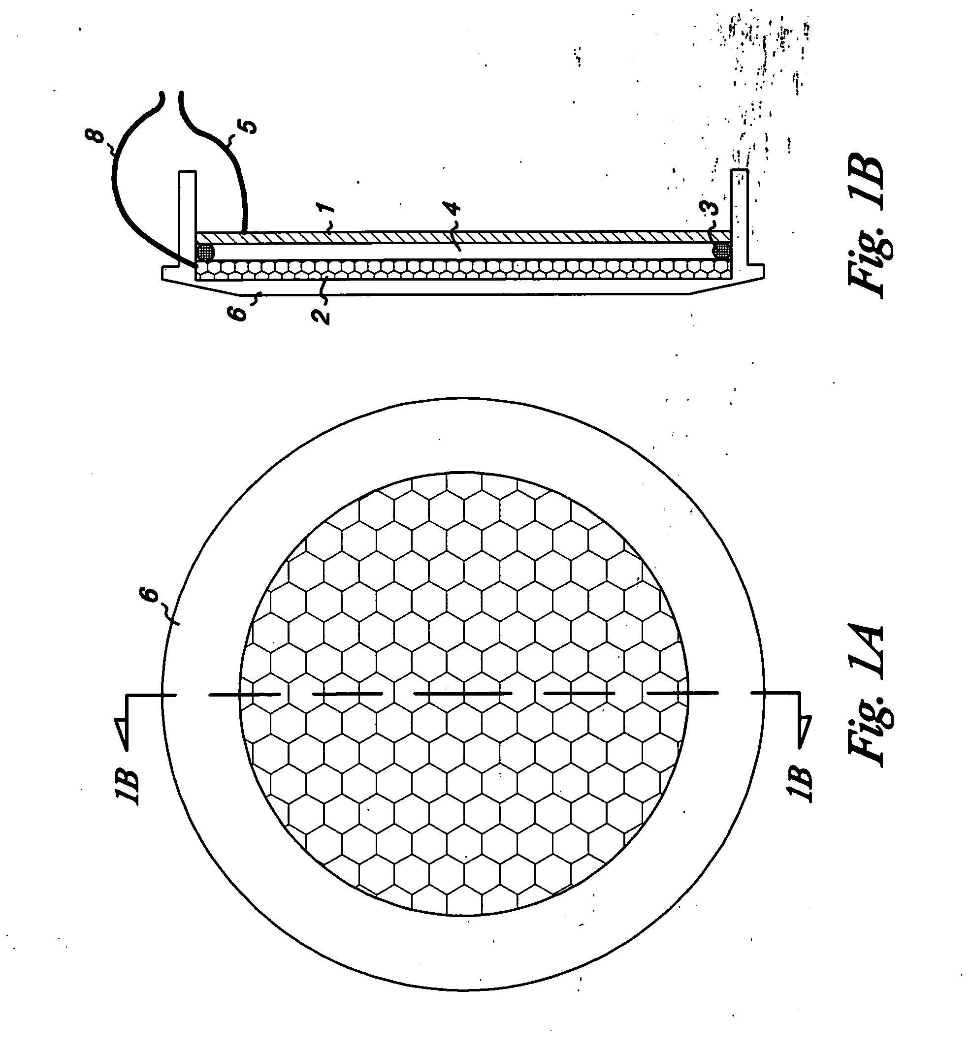
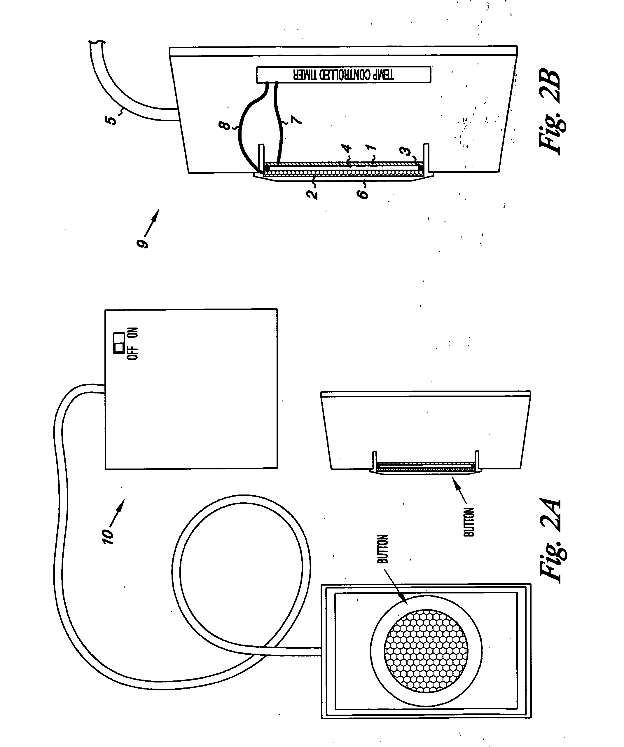
[0037] As shown in FIG. 1, the oxygen evolving anode 1 selected as the most efficient is an iridium oxide coated single sided sheet of platinum on a support of titanium (Eltech, Fairport Harbor, Ohio). The cathode 2 is a 1 / 16 inch mesh (size 8 mesh) marine stainless steel screen. The anode and cathode are separated by a non-conducting spacer 3 containing a gap 4 for the passage of gas and mixing of anodic and cathodic water and connected to a power source through a connection point 5. FIG. 2 shows a plan view of the assembled device. The O2 emitter 6 with the anode connecting wire 7 and the cathode connecting wire 8 is contained in an enclosure 9, connected to the battery compartment 10. The spacer thickness is critical as it sets the critical distance. It must be of sufficient thickness to prevent arcing of the current, but thin enough to separate the electrodes by no more than 0.140 inches. Above that thickness, the power needs are higher and the oxygen bubbles form...

example 2

Measurement of O2 Bubbles

[0041] Attempts were made to measure the diameter of the O2 bubbles emitted by the device of Example 1. In the case of particles other than gasses, measurements can easily be made by scanning electron microscopy, but gasses do not survive electron microscopy. Large bubble may be measured by pore exclusion, for example, which is also not feasible when measuring a gas bubble. A black and white digital, high contrast, backlit photograph of treated water with a millimeter scale reference was shot of water produced by the emitter of Example 1. About 125 bubbles were seen in the area selected for measurement. Seven bubbles ranging from the smallest clearly seen to the largest were measured. The area was enlarged, giving a scale multiplier of 0.029412.

[0042] Recorded bubble diameters at scale were 0.16, 0.22, 0.35, 0.51, 0.76, 0.88 and 1.09 millimeters. The last three were considered outliers by reverse analysis of variance and were assumed to be hydrogen bubbles...

example 3

Other Models of Oxygen Emitter

[0043] Depending on the volume of fluid to be oxygenated, the oxygen emitter of this invention may be shaped as a circle, rectangle, cone or other model. One or more may be set in a substrate that may be metal, glass, plastic or other material. The substrate is not critical as long as the current is isolated to the electrodes by the nonconductor spacer material of a thickness from 0.005 to 0.075 inches, preferably 0.050 inches. It has been noticed that the flow of water seems to be at the periphery of the emitter, while the evolved visible bubbles (H2) arise at the center of the emitter. Therefore, a funnel or pyramidal shaped emitter was constructed to treat larger volumes of fluid. FIG. 4 is a cross sectional diagram of such an emitter. The anode 1 is formed as an open grid separated from a marine grade stainless steel screen cathode 2 by the critical distance by spacer 3 around the periphery of the emitter and at the apex. This flow-through embodime...


PUM

PropertyMeasurementUnit
sizeaaaaaaaaaa
sizeaaaaaaaaaa
energyaaaaaaaaaa

Abstract

An oxygen emitter which is an electrolytic cell is disclosed. When the anode and cathode are separated by a critical distance, very small microbubbles and nanobubbles of oxygen are generated. The very small oxygen bubbles remain in suspension, forming a solution supersaturated in oxygen. A flow-through model for oxygenating flowing water is disclosed. The use of supersaturated water for enhancing the growth of plants is disclosed. Methods for applying supersaturated water to plants manually, by drip irrigation or in hydroponic culture are described. The treatment of waste water by raising the dissolved oxygen with the use of an oxygen emitter is disclosed.

Description

RELATED APPLICATIONS [0001] This application is a divisional application of U.S. patent application Ser. No. 10 / 372,326, filed on Dec. 10, 2003, which is a continuation-in-part of U.S. patent application Ser. No. 10 / 872,017, filed on Feb. 21, 2003, now U.S. Pat. No. 6,689,262, issued Feb. 10, 2004, which claims priority to U.S. Provisional Patent Application No. 60 / 358,534, filed Feb. 22, 2002.FIELD OF THE INVENTION [0002] This invention relates to the electrolytic generation of microbubbles of oxygen for increasing the oxygen content of flowing water. This invention also relates to the use of superoxygenated water to enhance the growth and yield of plants. The flow-through model is useful for oxygenating water for hydroponic plant culture, drip irrigation and waste water treatment. BACKGROUND OF THE INVENTION [0003] Many benefits may be obtained through raising the oxygen content of aqueous media. Efforts have been made to achieve higher saturated or supersaturated oxygen levels fo...

Claims


Application Information

Patent Timeline
Patent Type & Authority Applications(United States)
IPC IPC(8): A01G7/00A01G31/02A01K63/04C02FC02F1/461C02F1/467C02F1/68C02F1/72C02F3/26C02F7/00
CPCA01G31/00Y02E60/366A01K63/042C02F1/46109C02F1/4672C02F1/68C02F1/727C02F3/26C02F7/00C02F2001/46133C02F2001/46138C02F2001/46157C02F2201/4612C02F2201/4615C02F2209/02A01G31/02Y02E60/36Y02P60/21Y02W10/10
Inventor SENKIW, JAMES ANDREW
Owner OXYGENATOR WATER TECH
Learn More