Antenna arrangement having at least two decoupled antenna coils; RF component for non-contact transmission of energy and data; electronic device having RF component

a technology of antenna coils and antenna structures, applied in the direction of radiating elements structural forms, independent non-interfering antenna combinations, instruments, etc., can solve the problems of large energy consumption of transponders with their own energy supply, higher production costs, and inability to combine antenna structures with antenna structures of rfid chips or similar communication units, etc., to achieve high energy consumption, high quality, and high voltage plane

Inactive Publication Date: 2011-02-24
DEUT POST AG
View PDF7 Cites 9 Cited by
  • Summary
  • Abstract
  • Description
  • Claims
  • Application Information

AI Technical Summary

Benefits of technology

[0018]In the realm of radio frequency technology, an exemplary embodiment of the invention entails the essential advantage that two antennas can be used in one component without interfering with each other. The two antennas can be arranged in a small space and can even be operated at the same frequency. They can be, for example, two energy coils, two data coils or one data coil combined with one energy coil. Moreover, two transponders whose antennas do not interfere with each other can be implemented in one component. Consequently, different protocols such as, for example, ISO 14443 and ISO 15693 can be used for reading out transponders with differently configured antennas on one label. An additional security aspect may be achieved when several transponders with different frequencies are used.
[0019]Particularly when an exemplary embodiment of the invention is used on electronic devices, it may allow energy and data to be transferred wireles sly to electronic devices of the type that could not previously be operated with RF technology because of their high energy requirement. According to an exemplary embodiment, planar integration of several antenna structures in close proximity allows the use of several antennas having different requirements without having to substantially enlarge the size of an electronic device. Thus, different voltage planes can be provided, and the energy and data transmission can be separated from each other, whereby the requirements of both modalities of transmission may be met.
[0020]The transponder chip remains virtually unaffected by the energy transmission, and the associated antenna design can be standardized using an antenna of low quality. The energy coil, in turn, is of higher quality so that it can achieve the conceivably higher voltage planes. Through a systematic shift of the two coils with respect to each other, it is easy to achieve that the mutual inductance and thus also the coupling of the two coils are minimized or even equal to zero.
[0021]This has the advantage that both antennas can be dimensioned and optimized completely separately from each other. Such an optimization can comprise, for example, the selection of different bandwidths, a different number of windings, and different conductor widths.
[0022]An exemplary embodiment may provide the advantage that both antennas can be operated at the same frequency, as a result of which there is no need to provide a multi-antenna system on an associated reading and / or writing device.

Problems solved by technology

In contrast, active transponders with their own energy supply are larger and their production entails higher costs.
In fact, however, such antenna structures cannot be combined with antenna structures of an RFID chip or of similar communication units.
The voltage can be limited, for example, to 8-10 volts, meaning that higher voltages cannot be reached on the antenna.
Although the voltage could be subsequently increased by installing appropriate circuits, this is not desirable for reasons having to do with cost and functionality.
However, with a narrow-band antenna, which is desirable for efficient energy transmission, this is hardly or not at all possible.

Method used


Image

  • Antenna arrangement having at least two decoupled antenna coils; RF component for non-contact transmission of energy and data; electronic device having RF component
  • Antenna arrangement having at least two decoupled antenna coils; RF component for non-contact transmission of energy and data; electronic device having RF component
  • Antenna arrangement having at least two decoupled antenna coils; RF component for non-contact transmission of energy and data; electronic device having RF component

Examples


Embodiment Construction

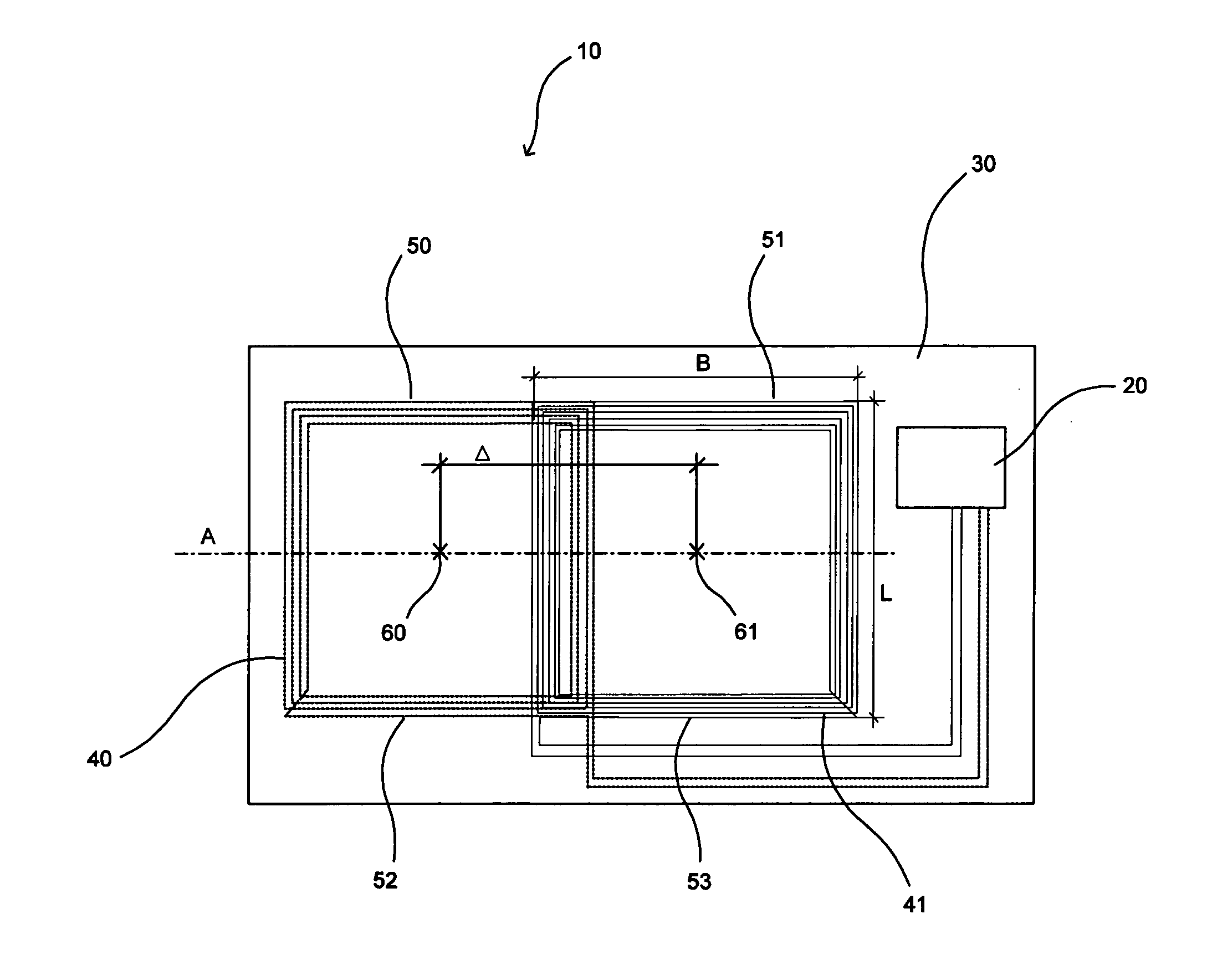
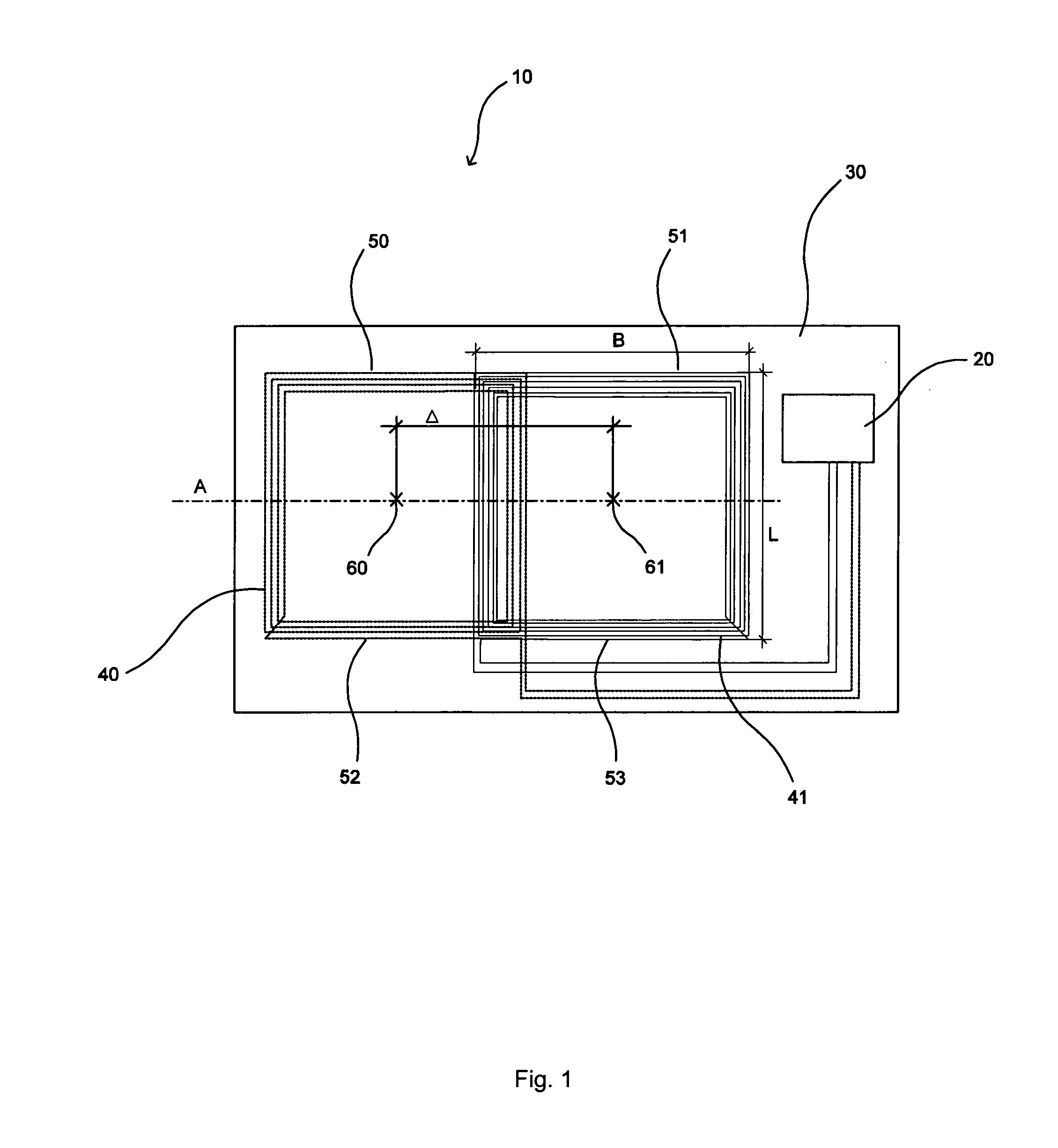
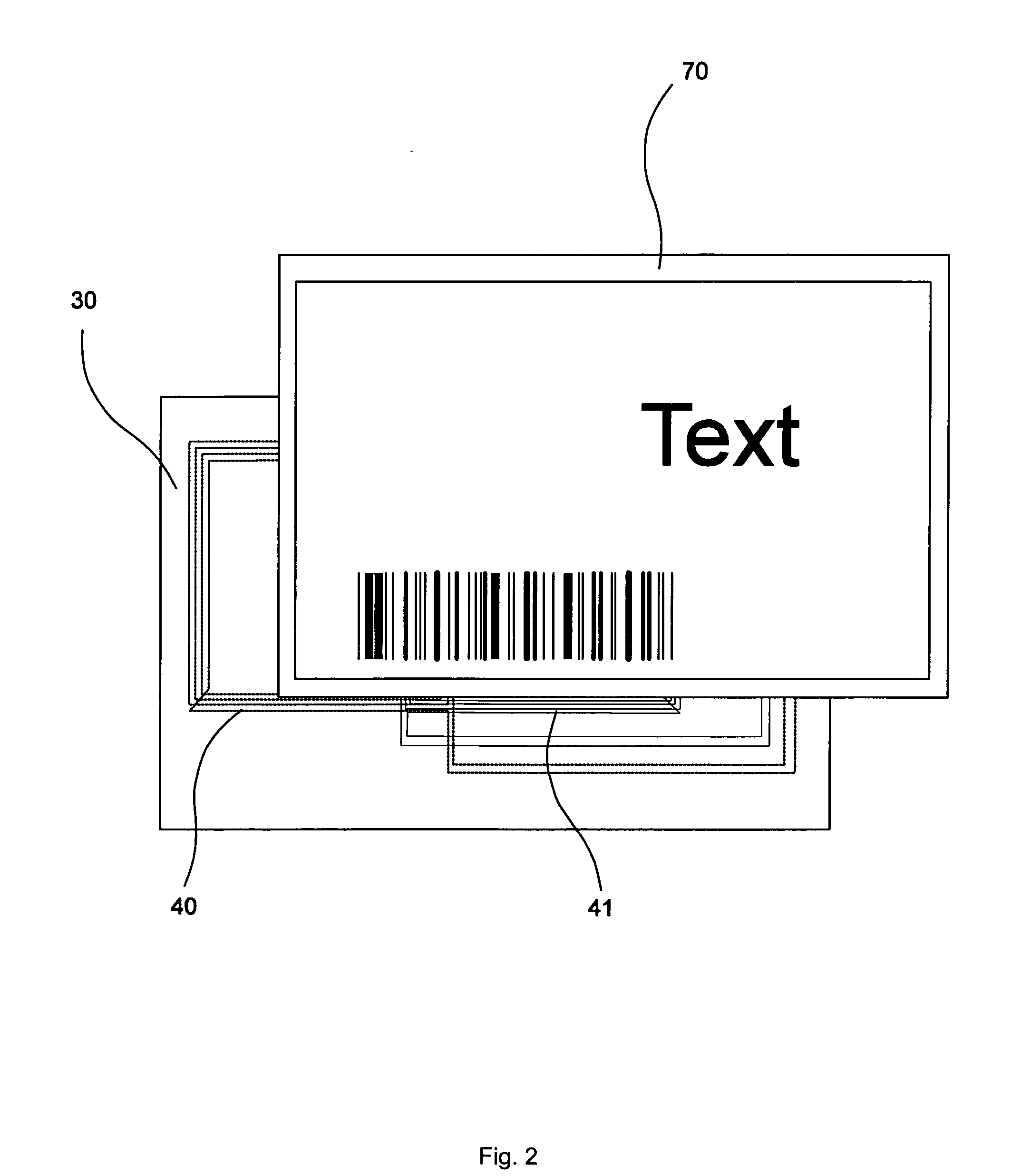
[0028]FIG. 1 shows an RF component according to an exemplary embodiment of the invention, whereby an RF component (RF=radio frequency) according to an exemplary embodiment is a component that receives and processes high-frequency radio signals. The term processing of radio signals means, among other things, the acquisition of energy from radio signals of a base station through induction and / or the modulation of an electromagnetic field of a base station.

[0029]The RF component 10 comprises at least of a non-conductive carrier 30 on which two antenna coils 40 and 41 and an electronic assembly such as, for example, a microchip 20 with an integrated circuit, are arranged. The carrier is preferably flat and plate-shaped. However, it can also comprise a film. The two antenna coils are connected to the microchip which, in turn, can be connected to an electronic device that is to be supplied with energy and data via the antennas. As an alternative, however, any other models and connections ...


PUM


Abstract

There is provided an antenna arrangement for RF systems. An exemplary antenna arrangement comprises at least two antenna coils that are installed on a flat, non-conductive carrier. The first antenna coil as well as the second antenna coil comprise one or more windings that are applied onto the carrier. The antenna coils are arranged in at least two different layers that are one above the other and that do not touch each other. The first antenna coil is of a first quality and the second antenna coil is of a second quality. The first antenna coil is arranged so as to be offset with respect to the second antenna coil in such a way that the mutual inductance between the two antenna coils is minimized.

Description

CROSS-REFERENCE TO RELATED APPLICATIONS[0001]Pursuant to 35 U.S.C. §371, this application is the United States National Stage Application of International Patent Application No. PCT / EP2009 / 001675, filed on Mar. 9, 2009, the contents of which are incorporated by reference as if set forth in their entirety herein, which claims priority to German (DE) Patent Application No. 10 2008 017 622.2, filed Apr. 4, 2008, the contents of which are incorporated by reference as if set forth in their entirety herein.BACKGROUND[0002]It is a known procedure to use antennas in the realm of contact-free energy and data transmission. Particularly in contact-free data transmission, RFID (Radio Frequency Identification) systems are used. Such a system normally consists of an RFID chip (transponder / tag) that is attached, for example, to an object, to a person or animal, or to a fixed position, and it also consists of one or more reading and / or writing devices. The RFID chip can be read and written by the r...

Claims


Application Information

Patent Timeline
Patent Type & Authority Applications(United States)
IPC IPC(8): H01Q7/00
CPCG06K19/07749G06K19/07767G06K19/07779G06K19/07781H01Q21/28H01Q1/38H01Q1/521H01Q7/00H01Q1/2225
Inventor REINHOLD, CHRISTIANSCHOLZ, PETER
Owner DEUT POST AG
Why Eureka
Try Eureka