Method for assembling a rotor with permanent magnets

a technology of permanent magnets and rotors, which is applied in the direction of rotating magnets, synchronous machines with stationary armatures, stator/rotor bodies, etc., can solve the problems of reducing the performance of the motor, high cost and temperature sensitive methods, and difficult to introduce permanent magnets in the recesses provided for this purpose in the lamellae, etc., and achieves high energy requirements.

Active Publication Date: 2014-03-25
ATLAS COPCO AIRPOWER NV
View PDF13 Cites 2 Cited by
  • Summary
  • Abstract
  • Description
  • Claims
  • Application Information

AI Technical Summary

Benefits of technology

[0013]It is known that this incorrect orientation can be avoided by mounting the magnets in non-magnetised state in the rotor and magnetize them afterwards, together with the whole rotor, but this way of magnetising has the disadvantage of involving a high energy requirement.

Problems solved by technology

A disadvantage of this method is that the local connections between the isolated lamellae result in a reduced performance of the motor, since they have a negative influence on the iron losses induced by the magnetic field.
A disadvantage is that when sticking the lamellae together by means of adhesives, this method is expensive and sensitive to temperature.
Another disadvantage is that it is difficult to introduce the permanent magnets in recesses provided for this purpose in the lamellae that are already joined together.
Another disadvantage of the lamellae that have already been joined is the possibility to make mistakes by mounting the magnets in an incorrect orientation in the recesses provided for this purpose, more specifically with the north-south direction of the magnets opposite to the intended north-south direction.
It is known that this incorrect orientation can be avoided by mounting the magnets in non-magnetised state in the rotor and magnetize them afterwards, together with the whole rotor, but this way of magnetising has the disadvantage of involving a high energy requirement.

Method used


Image

  • Method for assembling a rotor with permanent magnets
  • Method for assembling a rotor with permanent magnets
  • Method for assembling a rotor with permanent magnets

Examples


Embodiment Construction

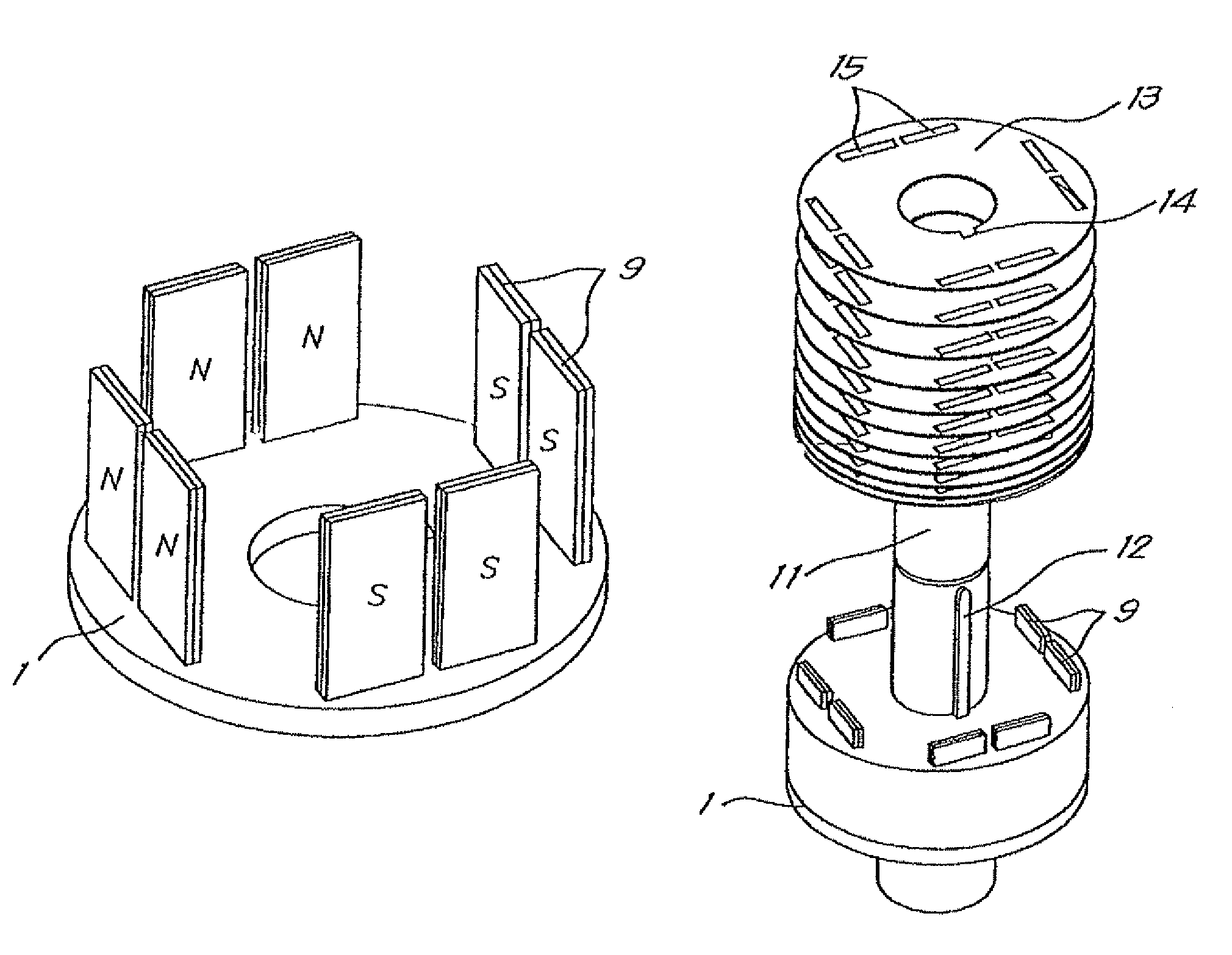
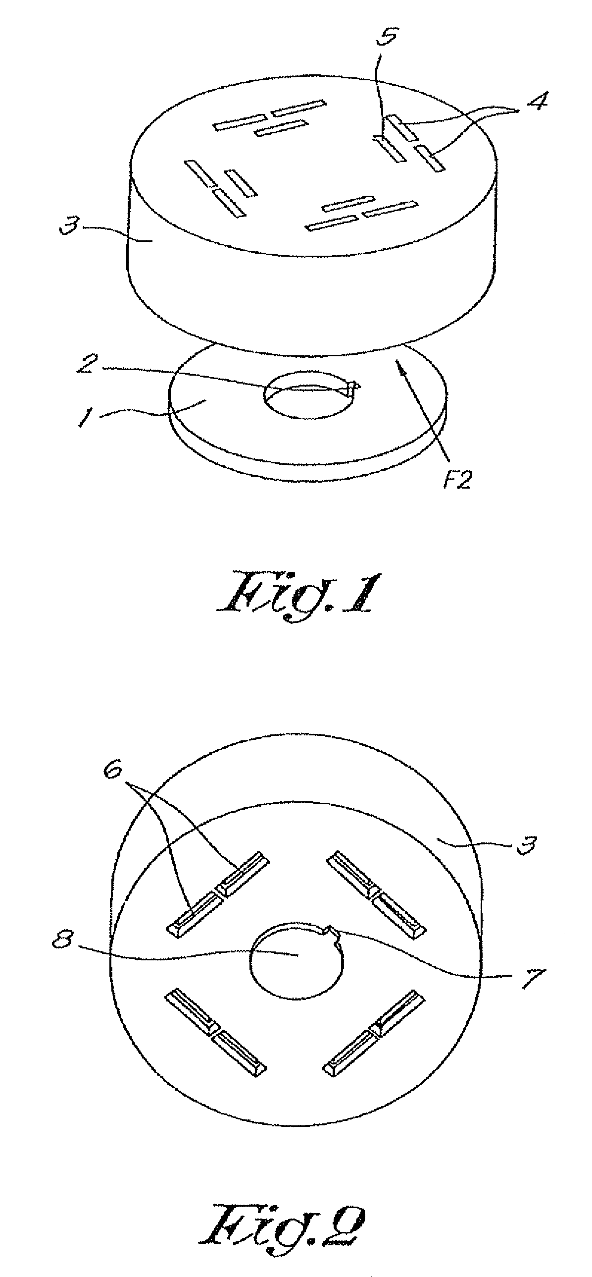
[0045]FIG. 1 shows a non-ferromagnetic support plate 1 which in this example is disc-shaped and demonstrates a preferably centrally located, through, round hole, as well as a recess 2 that in this case consists of a notch in the circumferential wall of the said central hole.

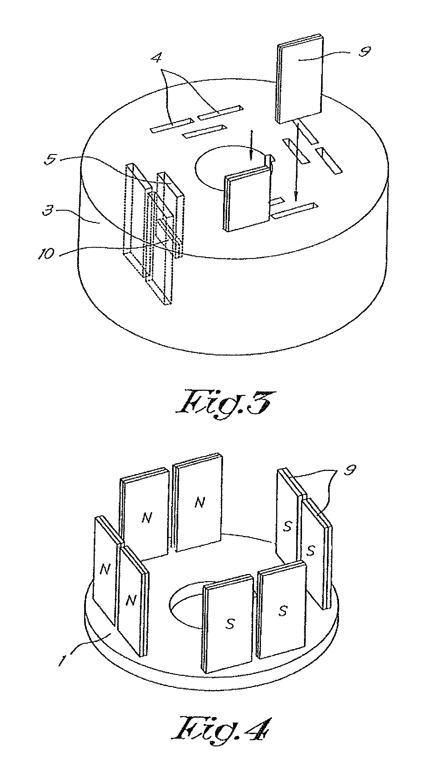
[0046]On the aforementioned support plate 1 a non-ferromagnetic holder 3 can be placed, whereby in this case said holder 3 shows also a disc-shape and whereby this holder 3 is provided with recesses 4 extending in the axial direction and which, in this case, continue through the entire thickness of the holder 3, and with recesses 5 which, in this case, only continue up to the half of the depth of the holder.

[0047]As represented in FIG. 2 the exits 6 of the recesses 4 through the holder 3 are visible on one axial end of the holder 3, which exits 6 are widened towards the end plane of the concerning axial end.

[0048]The concerning end plane is also provided with a keyway 7 which together with a disc-shaped protubera...


PUM

PropertyMeasurementUnit
pressureaaaaaaaaaa
distanceaaaaaaaaaa
magnetic fieldaaaaaaaaaa

Abstract

Method for assembling a rotor with permanent magnets, including the steps of introducing the magnets in 10 recesses of a non-ferromagnetic holder; combining the holder and the permanent magnets with a non-ferromagnetic support plate; attaching the permanent magnets to the support plate; and removing the holder and providing lamellae over the permanent magnets attached to the support plate. A holder and rotor obtained by the method are described.

Description

BACKGROUND OF THE INVENTION[0001]1. Field of the Invention[0002]The present invention relates to a method for assembling a rotor with permanent magnets, a holder applied thereby, and a rotor obtained by such a method.[0003]2. Related Art[0004]More specifically, the invention is intended for assembling such a rotor for use in interior permanent magnet motors (IPM).[0005]In standard induction motors the rotor is composed of ferromagnetic lamellae, which are held together by a cage, usually made by injection moulding.[0006]Motors with a laminated rotor are also known, whereby permanent magnets are positioned in ferromagnetic lamellae, and which motors, as result thereof, do not have a cage and require another way of compressing and holding the lamellae together.[0007]It is known that when assembling this last type of motor the lamellae are first joined together in a stack and are mutually attached, for which different methods are already known.[0008]For instance, it is possible to punc...

Claims


Application Information

Patent Timeline
Patent Type & Authority Patents(United States)
IPC IPC(8): H02K15/03
CPCH02K15/03H02K1/276Y10T29/49012
Inventor DESIRON, ANDRIES, JAN, F.
Owner ATLAS COPCO AIRPOWER NV
Why Eureka
Try Eureka