Product dispensing cap with pivotal directional spout

a technology of product dispensing cap and pivotal spout, which is applied in the direction of liquid transfer device, roads, roads, etc., can solve the problems of reducing the value of containers, heavy and tiresome to grasp and hold upside down, and reducing the volume of containers

Inactive Publication Date: 2008-11-04
C & N PACKAGING +1
View PDF31 Cites 17 Cited by
  • Summary
  • Abstract
  • Description
  • Claims
  • Application Information

AI Technical Summary

Benefits of technology

[0010]The present invention is directed to a dispensing cap for dispensing material from a container having a mouth. The cap comprises a main body mountable on the mouth of the container. The main body includes a protruding portion having a passageway for receiving and passing therethrough material flowing through the mouth, with the protruding portion having a plurality of sides. The protruding portion is disposed on the main body such that a space is formed adjacent one side of the plurality of sides of the protruding portion. The dispensing cap also includes a combination seal and dispensing spout pivotally mounted to the main body, with the spout having a top wall and an extended portion joined to the top wall, and two side walls coupled to the top wall. The spout is pivotal between a sealing position such that the spout substantially prevents flow of material through the passageway and a dispensing position such that material can be dispensed by flowing through the mouth and the passageway and onto the spout, wherein upon the spout pivoting on the main body from the sealing position to the dispensing position, the extended portion pivots through the space and contacts at least one of the plurality of sides of the protruding portion of the main body.

Problems solved by technology

One drawback, however, with the lid disclosed therein is that the container on which the lid is affixed and which holds the granular material to be distributed must be held in an upside down position and grasped from its bottom in order for the lid to function.
Users may feel it awkward to hold the container in such a position, and a filled container may be heavy and tiresome to grasp and hold upside down.
Such provision may diminish valuable container volume, and further may offset the stability of the container while it rests on its bottom when not in use.

Method used


Image

  • Product dispensing cap with pivotal directional spout
  • Product dispensing cap with pivotal directional spout
  • Product dispensing cap with pivotal directional spout

Examples


Embodiment Construction

[0026]For the purposes of promoting an understanding of the principles of the invention, reference will now be made to the embodiment illustrated in the drawings and specific language will be used to describe the same. It will nevertheless be understood that no limitation of the scope of the invention is thereby intended, such alterations and further modifications in the illustrated device, and such further applications of the principles of the invention as illustrated therein being contemplated as would normally occur to one skilled in the art to which the invention relates.

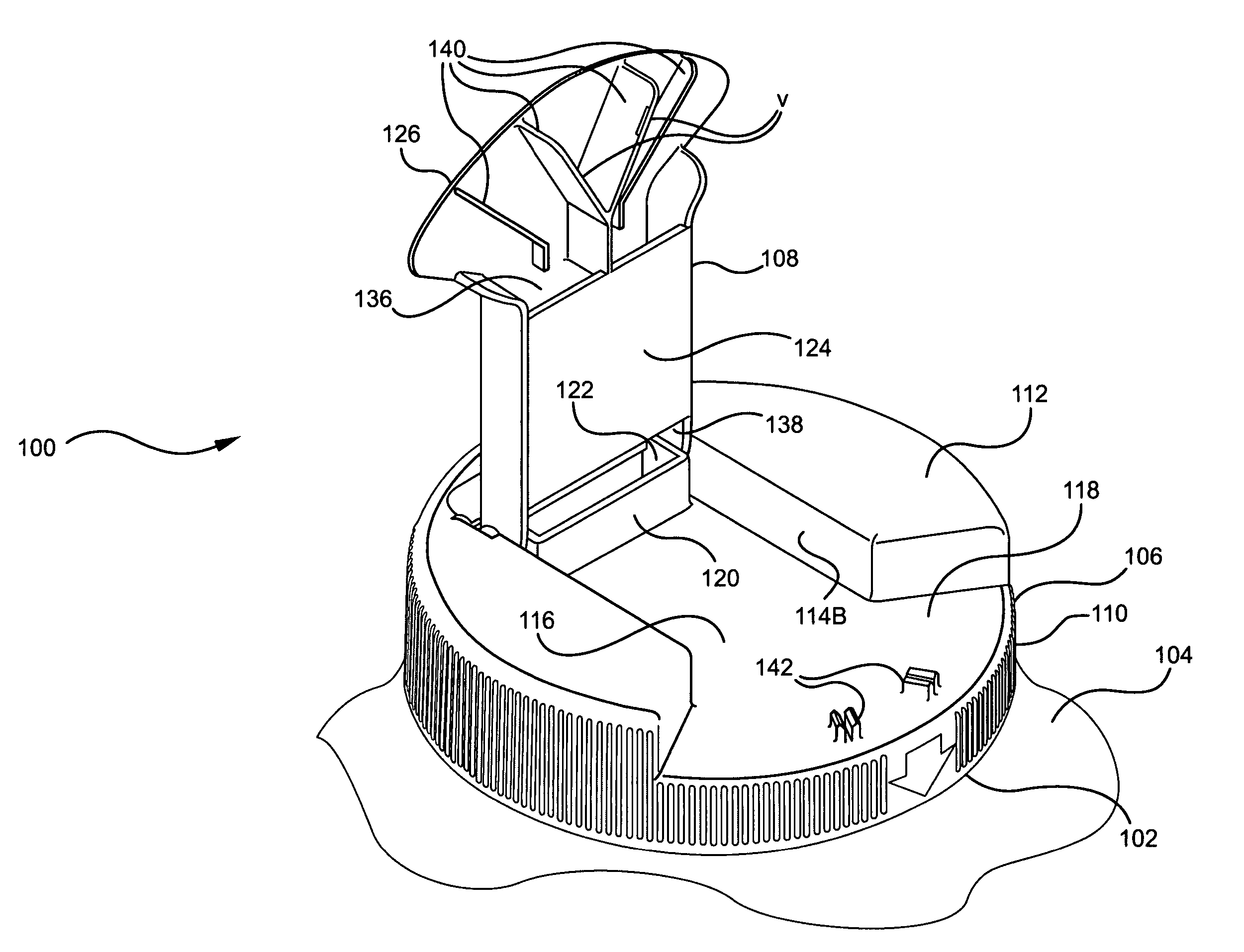
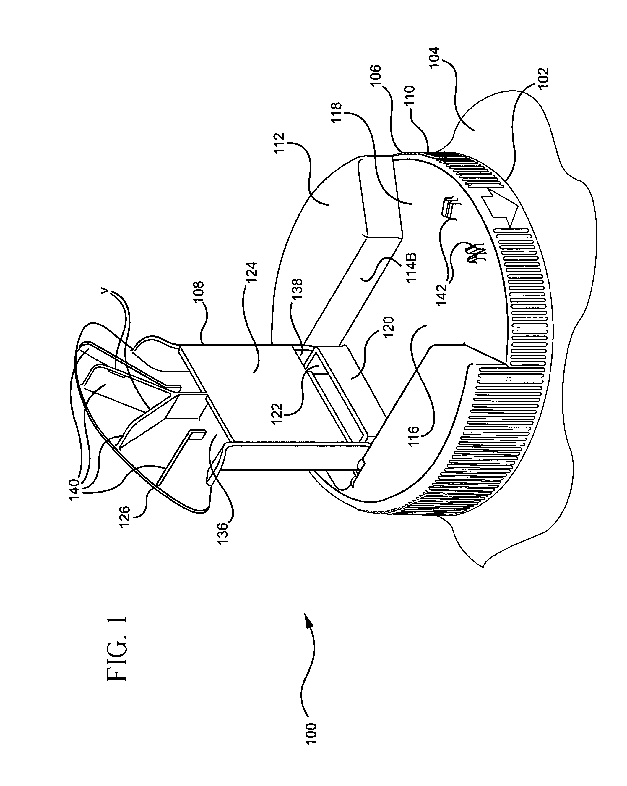
[0027]Referring initially to FIG. 1, there is shown a cap 100 of the present invention for dispensing material from a mouth 102 of a container 104. Only the top portion of the container 104 is depicted in the drawings, it being understood that the main body of the container further extends from the mouth 102 as shown in FIG. 1. The interior of the container 104 can be filled with a fluidized material, such as a ...


PUM


Abstract

A cap dispenses material from a container having a mouth. The cap has a main body mountable on the mouth. The main body includes a protruding portion having an opening for receiving material moving through the mouth. A combination seal and dispensing spout is pivotally mounted to the main body and has a top wall with an extended portion. The spout may be pivoted on the main body between a sealing position and a dispensing position. In the sealing position, the spout blocks flow of material through the opening. In the dispensing position, the spout is aligned with the opening in the protruding portion to allow material to flow through the protruding portion and onto the spout so that the material may be dispensed.

Description

BACKGROUND OF THE INVENTION[0001]The present invention relates generally to the field of containers and lids for dispensing fluidized material.DESCRIPTION OF THE PRIOR ART[0002]A variety of containers and lids have been devised for spreading fluidized material, such as grass seed, fertilizer, food products and various granular and powdered material. For example, U.S. Pat. No. 1,274,969 discloses a broadcast sower for distributing seed from a container in a plurality of different directions. U.S. Pat. No. 2,511,560 discloses a scoop for manually scattering powdered or granular materials such as lime, fertilizer, or seeds with the scoop provided with a plurality of vanes to direct the material outwardly from the scoop. Another seed spreader that inertially ejects the seed from the hopper is disclosed in U.S. Pat. No. 4,773,568. A simpler approach is disclosed in U.S. Pat. No. 4,998,674 that includes a telescopic nozzle to uniformly distribute granular material. U.S. Pat. No. 5,938,062...

Claims


Application Information

Patent Timeline
Patent Type & Authority Patents(United States)
IPC IPC(8): A01C3/06B67D3/00B67D7/06
CPCA01C7/02A01C15/02B65D47/2006B65D83/06
Inventor YOUNG, CHRISTOPHER J.MARKERT, BROOKS R.CAVERO, DIO C.LESLIE, STUARTWALDINGER, JUSTIN
Owner C & N PACKAGING
Why Eureka
Try Eureka