Sheet conveying apparatus

a conveying apparatus and sheet technology, applied in the direction of registering devices, thin material processing, article separation, etc., can solve the problems of irregularity or the like of the image position, and achieve the effect of reducing the influence of the accuracy of the image forming position and the accuracy or irregularity of the right angl

Inactive Publication Date: 2008-11-04
CANON KK
View PDF16 Cites 38 Cited by
  • Summary
  • Abstract
  • Description
  • Claims
  • Application Information

AI Technical Summary

Benefits of technology

[0012]So, the present invention has been made in order to solve such problems, and has as its object to provide a sheet conveying apparatus and an image forming apparatus which can reduce the influence of the accuracy of an image forming position and the accuracy or irregularity of the right angle of a sheet during the processing of the sheet.

Problems solved by technology

Accordingly, when in the conventional sheet conveying apparatus, such a technique as described above which corrects the attitude of the sheet with the leading edge or the side edge of the sheet as the reference, the following problem arises.
That is, in a case where the accuracy of the right angle of the sheet is low or in a case where the degree of the right angle of the sheet is irregular, when an image is to be formed on the sheet, deviation occurs to the image forming position, and during the processing of the sheet, the irregularity or the like of an image position occurs.

Method used


Image

  • Sheet conveying apparatus
  • Sheet conveying apparatus
  • Sheet conveying apparatus

Examples


first embodiment

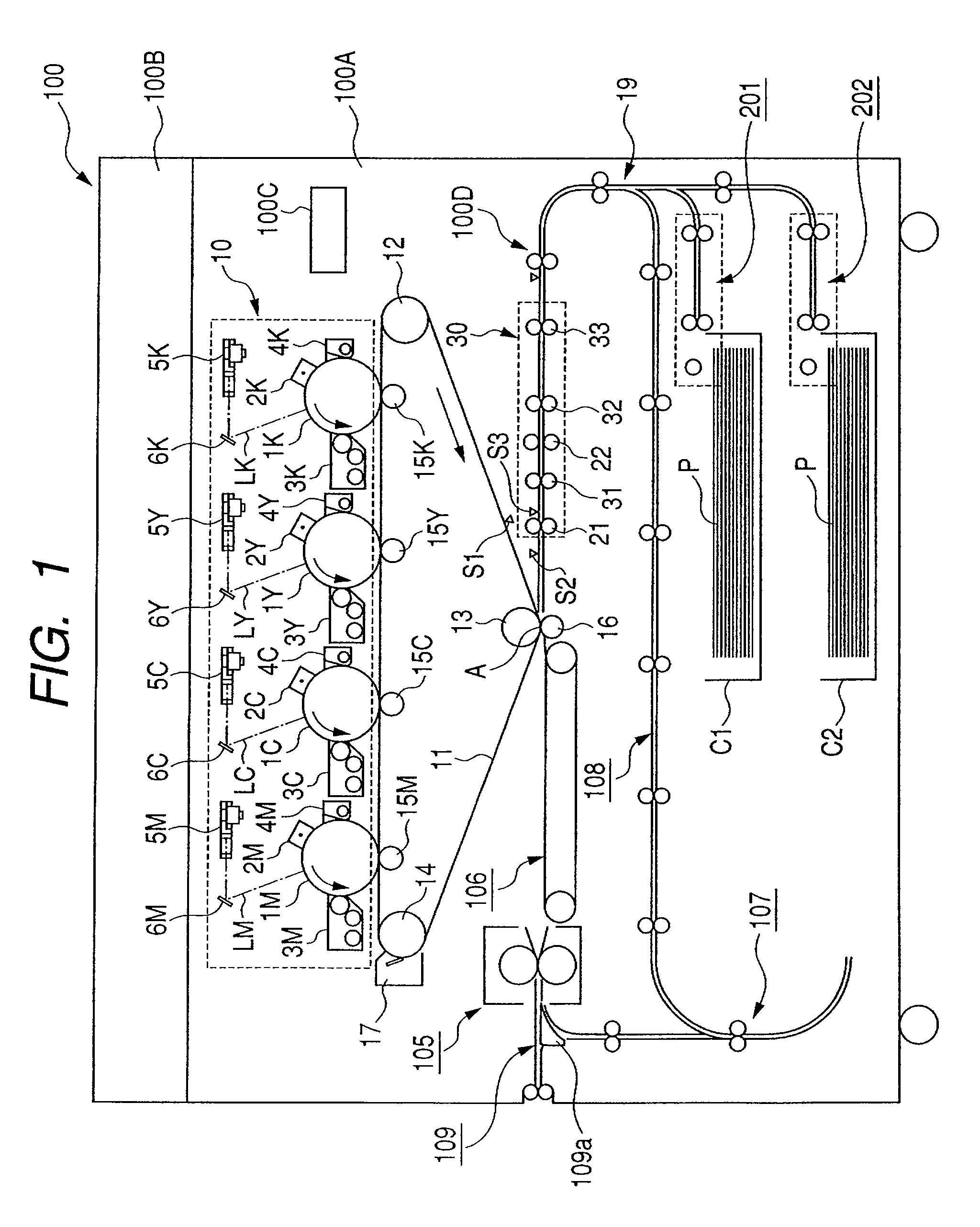
[0038]FIG. 1 schematically shows the construction of a digital full-color copying machine having a printer function and a copying machine function which is an example of an image forming apparatus provided with a sheet conveying apparatus according to the present invention.

[0039]In FIG. 1, the reference numeral 100 designates the digital full-color copying machine, the reference character 100A denotes a digital full-color copying machine main body (hereinafter referred to as the copying machine main body), and an image reading device 100B is provided on the upper surface of this copying machine main body 100A. Also, an image forming portion 10 is provided in the upper portion of this copying machine main body 100A, and cassette sheet feeding portions 201 and 202 for feeding sheets P contained in cassettes C1 and C2 are provided in the lower portion thereof.

[0040]The sheets P contained in the cassettes C1 and C2 are fed out one by one by the cassette sheet feeding portions 201 and 20...

second embodiment

[0095]the present invention will now be described.

[0096]FIG. 18 schematically shows the construction of a digital full-color copying machine which is an example of an image forming apparatus provided with a sheet conveying apparatus according to the present embodiment. In FIG. 18, the same reference characters as those in FIG. 1 designate the same or corresponding portions.

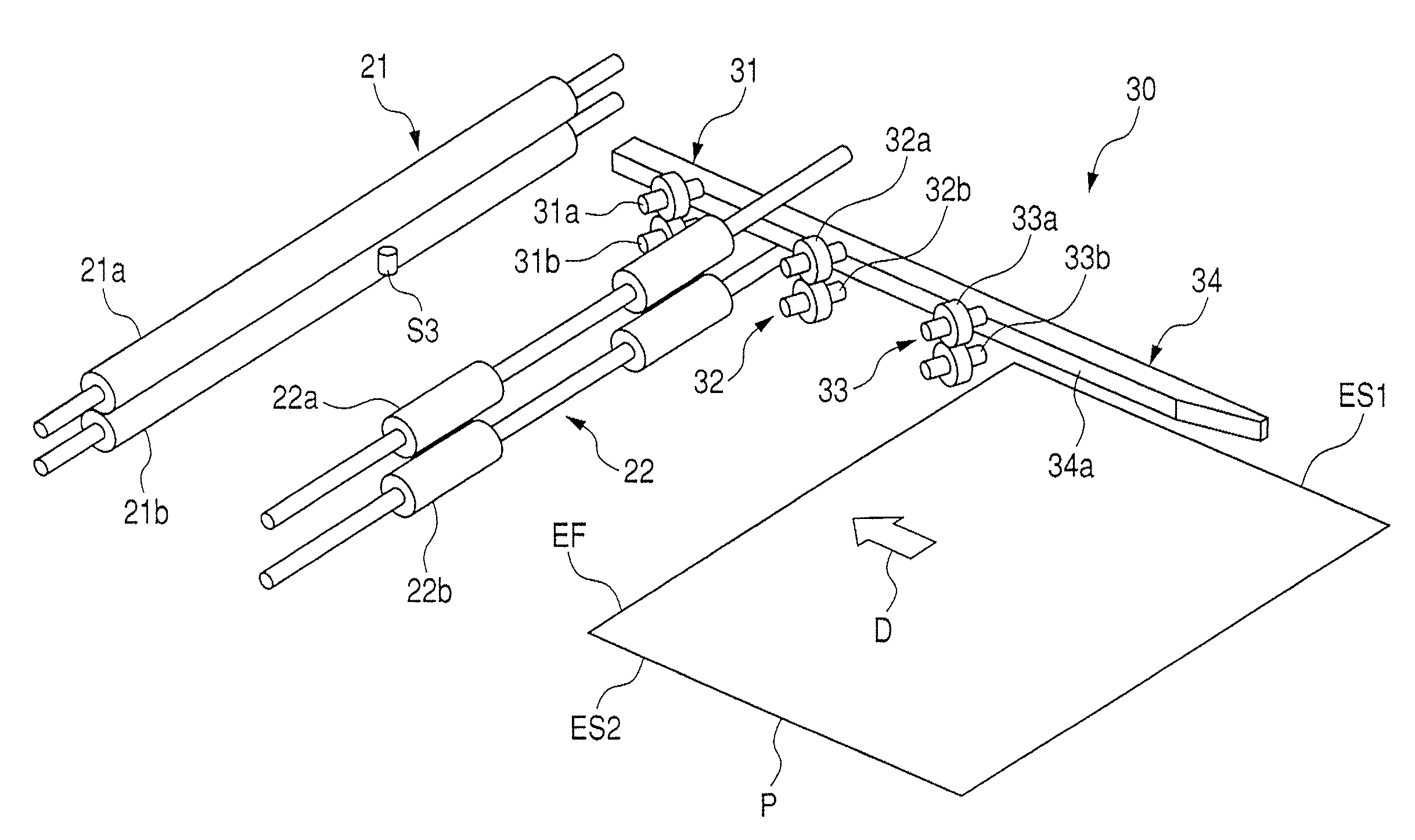
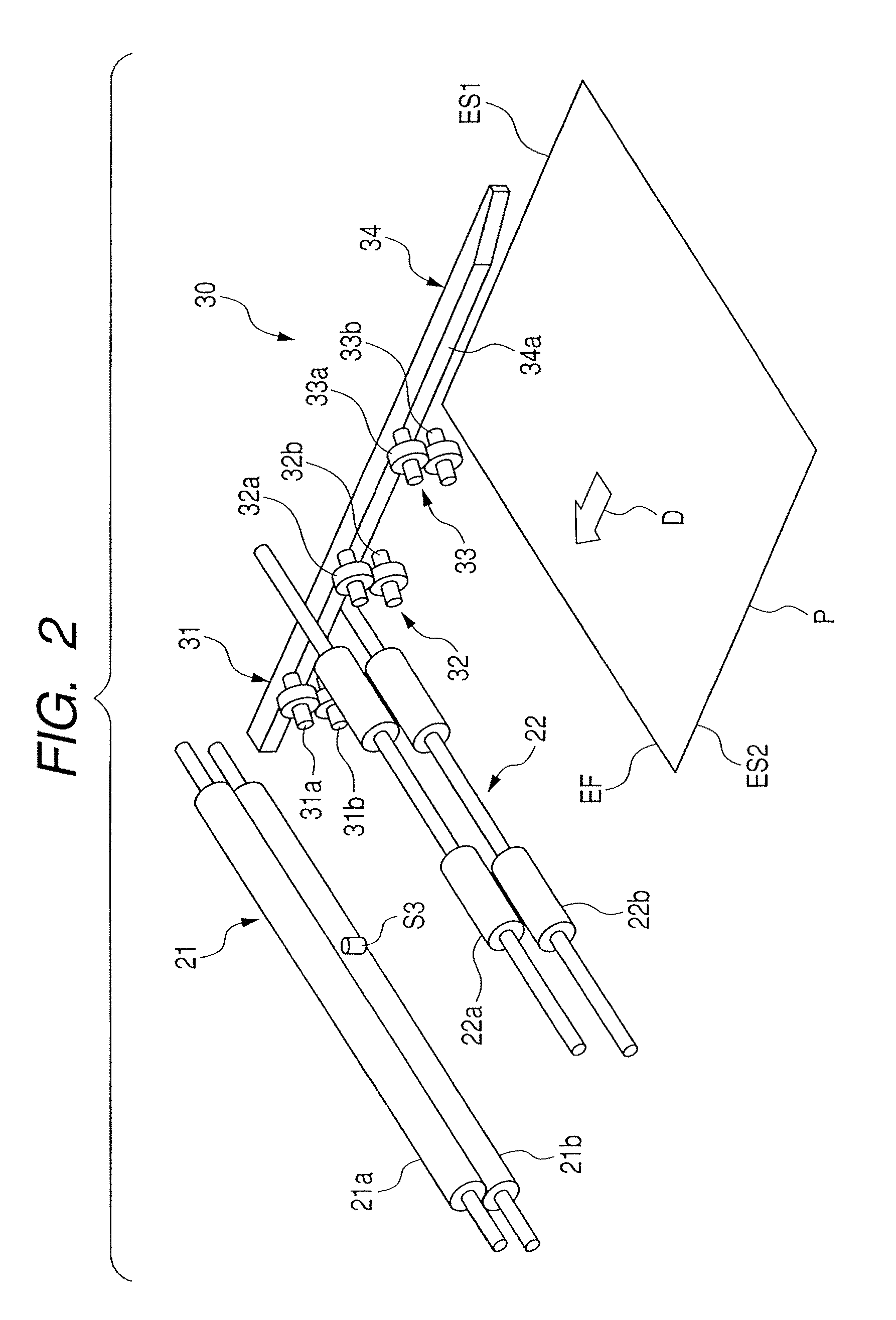
[0097]In FIG. 18, the reference numeral 50 denotes a sheet aligning device provided in the sheet conveying apparatus 100D for controlling the attitude and position of a sheet. This sheet aligning device 50 is provided with a pair of attitude controlling rollers 51 and 52, a pair of registration rollers 21 for conveying the sheet P to the secondary transferring portion A in timed relationship with an image on the transfer belt 11, and a pair of relay conveying rollers 53. In the present embodiment, the pair of registration rollers 21 and movable in the width direction by a moving mechanism (not shown).

[0098]FIG. 19...


PUM


Abstract

A sheet conveying apparatus for conveying a sheet to an image forming portion has a first aligning member for effecting the alignment of the sheet with one of the opposite side edges of the sheet parallel to a sheet conveying direction as a reference, a second aligning member for effecting the alignment of the sheet with the leading edge of the sheet orthogonal to the sheet conveying direction as a reference, and an aligning operation controlling device for selectively operating one of the first aligning member and the second aligning member on the basis of at least one of image information, sheet information and sheet processing information.

Description

BACKGROUND OF THE INVENTION[0001]1. Field of the Invention[0002]The invention relates to a sheet conveying apparatus, in particular, an apparatus for aligning a sheet.[0003]2. Description of the Related Art[0004]Heretofore, in an image forming apparatus such as a copying machine or a printer, a toner image formed on an image bearing member such as a photosensitive drum in an image forming portion has been transferred to a sheet, and thereafter has been fixed on the sheet by fixing means such as heat fixing means or pressure fixing means to thereby effect image formation.[0005]Such an image forming apparatus is provided with a sheet conveying apparatus for conveying the sheet to the image forming portion. Such a sheet conveying apparatus is provided with a sheet aligning portion for correcting the skew feed or position of the sheet being conveyed, and the skew feed or position of the sheet is corrected by this sheet aligning portion to thereby prevent the deviation of the image forme...

Claims


Application Information

Patent Timeline
Patent Type & Authority Patents(United States)
IPC IPC(8): B65H9/00
CPCB65H9/006B65H9/166B65H2404/1442B65H2404/7412B65H2220/09
Inventor ONODERA, SHINICHI
Owner CANON KK
Why Eureka
Try Eureka