Stepped labyrinth seal

a technology of labyrinth seals and stepped labyrinths, which is applied in the field of labyrinth seals, can solve the problems of reducing the carry-over effect and less effective prior art seals, and achieve the effect of not slowing down the leakage flow

Inactive Publication Date: 2008-11-04
FLORIDA TURBINE TECH
View PDF13 Cites 94 Cited by
  • Summary
  • Abstract
  • Description
  • Claims
  • Application Information

AI Technical Summary

Benefits of technology

[0016]A stepped labyrinth seal used in a liquid or gaseous device in which the assembly includes a series of stepped portions that form gaps with fingers extending toward the stepped portions. Downstream from the gap is a curved surface that causes the leakage flow through the gap to be reversed in direction about 180 degrees and directed against a curved portion on the finger into the labyrinth cavity without slowing the leakage flow. The flow passes through a second gap and into a second curved surface to reverse the flow and direct the flow onto a curved surface of the second finger so that the leakage flow continues to flow without increasing pressure due to significant drop in the kinetic energy of the leakage flow through the stepped gaps. This flow reduces the carry-over effect which makes the Prior Art seals less effective. The present invention produces an improved stepped labyrinth seal over the prior art devices.

Problems solved by technology

This flow reduces the carry-over effect which makes the Prior Art seals less effective.

Method used


Image

  • Stepped labyrinth seal
  • Stepped labyrinth seal
  • Stepped labyrinth seal

Examples


Embodiment Construction

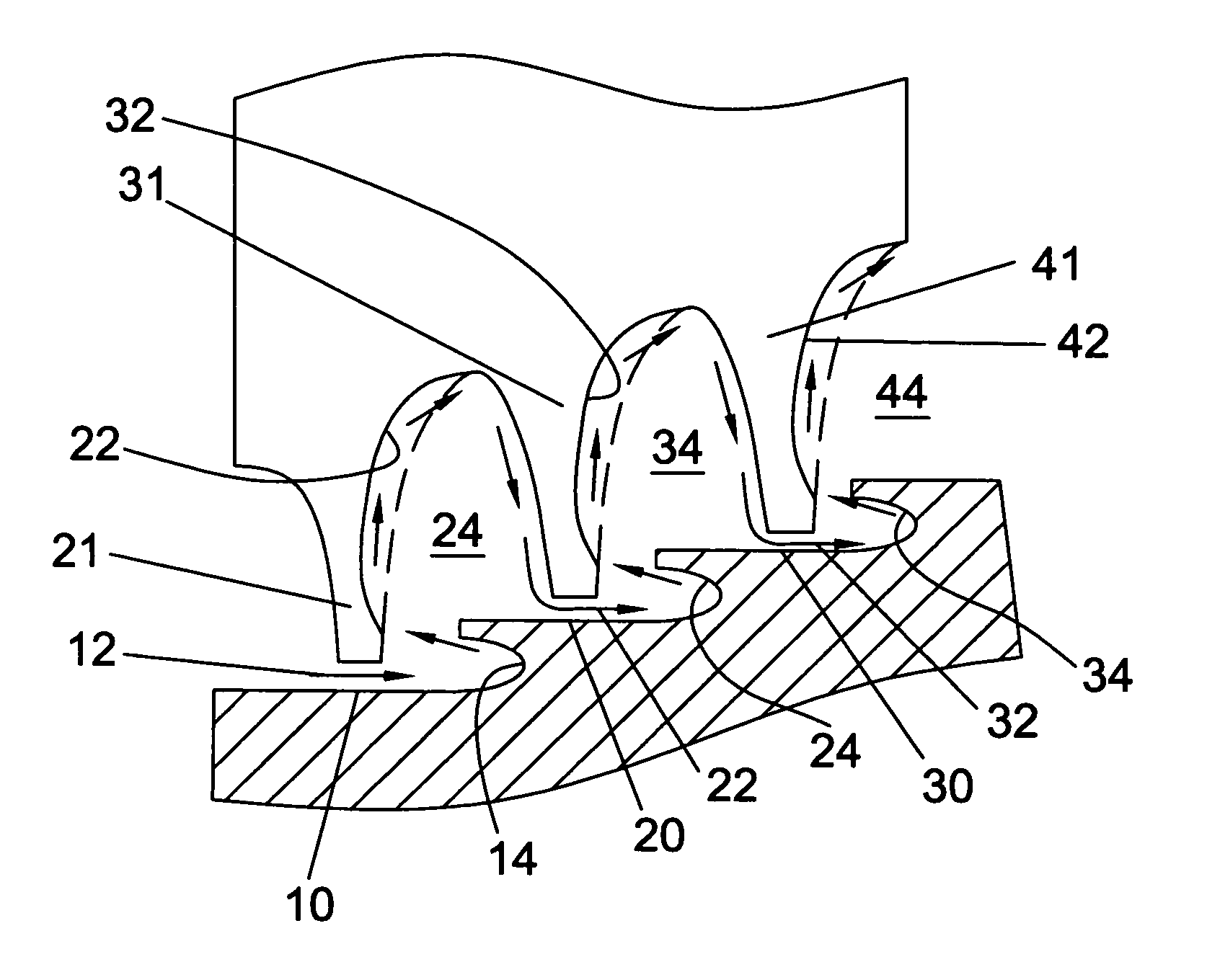
[0023]The stepped labyrinth seal of the present invention is shown in FIGS. 4 and 5. FIG. 4 shows a first embodiment in which a land (the rotating part with the plurality of fingers (21, 31, 41) rotates about a runner having the stepped portions (10, 20, 30). As an alternative to the first embodiment, the stepped portions could be the rotating part, while the fingers could be the stationary part without departing from the spirit of the present invention.

[0024]The land includes a plurality of fingers (21, 31, 41) extending there form and forming a gap 12 with the stepped portions (10, 20, 30) of the runner. A leakage flow first redirecting groove 14 is formed in the stepped portion 10 to redirect the flow. The first finger 21 of the land includes a first undercut portion 22 formed in the first finger 21 to receive the redirected flow from the first redirecting groove 14 for the purpose of passing the flow into the first cavity 24 without slowing the flow down such that the static pre...


PUM


Abstract

A stepped labyrinth seal for a turbomachine, the seal having a stepped portion with a redirecting groove formed thereon to redirect a leakage flow through the gap in substantially a reverse direction and onto a surface of the finger such that the dynamic pressure of the leakage flow is not substantially reduced and the static pressure increased. The cavity formed between adjacent fingers has a flow guiding surface that maintains the dynamic pressure of the flow, thereby keeping the flow at high velocity and low static pressure.

Description

CROSS-REFERENCE TO RELATED APPLICATIONS[0001]None.STATEMENT REGARDING FEDERALLY SPONSORED RESEARCH OR DEVELOPMENT[0002]None.BACKGROUND OF THE INVENTION[0003]1. Field of the Invention[0004]The present invention relates generally to a labyrinth seal, and more specifically to a labyrinth seal is a turbomachine.[0005]2. Description of the Related Art including information disclosed under 37 CFR 1.97 and 1.98[0006]Labyrinth seals are often used to reduce or control fluid leakage in systems having equipment such as gas and steam turbines, compressors, pumps, and other types of rotating equipment where fluid flow may occur between two relatively rotating members. More particularly, labyrinth seals are frequently used in sealing between elements such as a rotating shaft and an associated stator housing to inhibit undesirable fluid flow between the exterior of the shaft and interior of the stator. When incorporated with a pump, a labyrinth seal may be relied upon to inhibit leakage along the...

Claims


Application Information

Patent Timeline
Patent Type & Authority Patents(United States)
IPC IPC(8): F16J15/447
CPCF01D11/02F16J15/4472F05D2250/70F05D2250/712
Inventor PELFREY, PHILIP C.
Owner FLORIDA TURBINE TECH
Why Eureka
Try Eureka