Ink-jet cartridge removal device

a cartridge and inkjet technology, applied in printing and other directions, can solve the problems of difficult cartridge removal, molded features, expensive and time-consuming production, etc., and achieve the effect of convenient cartridge removal, convenient manual cartridge removal, and convenient cartridge removal

Inactive Publication Date: 2008-11-04
NU KOTE INT
View PDF13 Cites 1 Cited by
  • Summary
  • Abstract
  • Description
  • Claims
  • Application Information

AI Technical Summary

Benefits of technology

[0013]One advantage of the present invention is the provision of a ledge formed in the cartridge lid to facilitate manual removal of the cartridge from a printer.
[0014]Another advantage of the present invention is the provision of a tab formed on the cartridge lid to facilitate removal of the cartridge from the printer.
[0015]Still another advantage of the present invention is the provision of indentations formed in the lid and side walls of the cartridge to facilitate removal of the cartridge from the printer.
[0016]Still other aspects and advantages of the invention will become apparent to those skilled in the art upon reading and understanding the following detailed description.

Problems solved by technology

The removal features being built into the cartridge and printhead latch make it difficult to remove the cartridge if the features were to break while installing or removing the cartridge from the printhead.
Furthermore, these molded features, often in the form of projecting portions which engage the printhead, are expensive and time-consuming to produce.

Method used


Image

  • Ink-jet cartridge removal device
  • Ink-jet cartridge removal device
  • Ink-jet cartridge removal device

Examples


Embodiment Construction

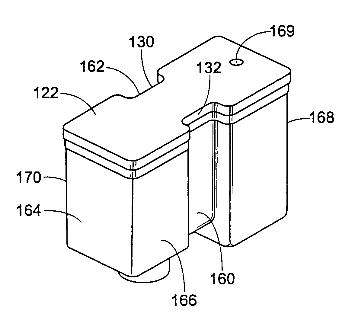
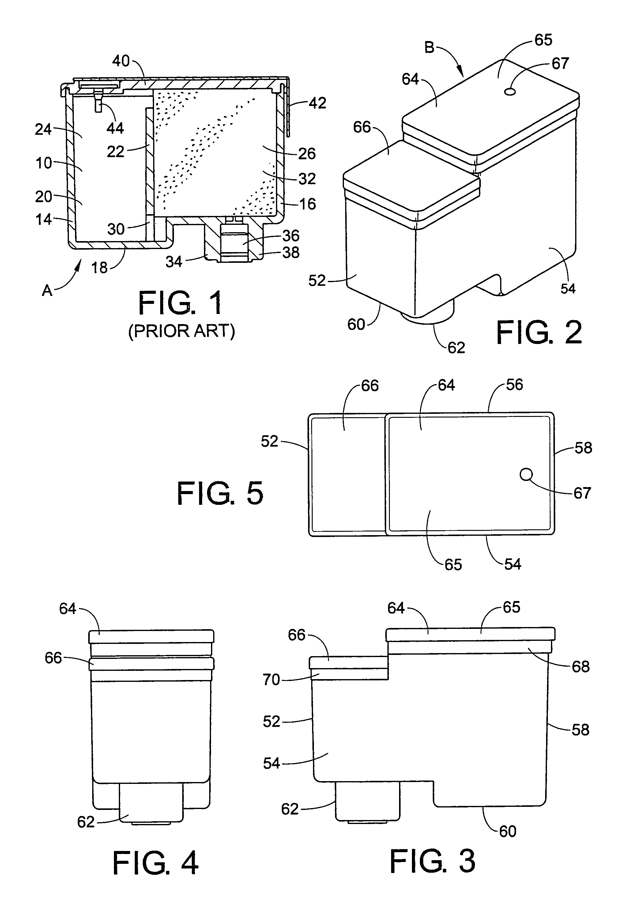
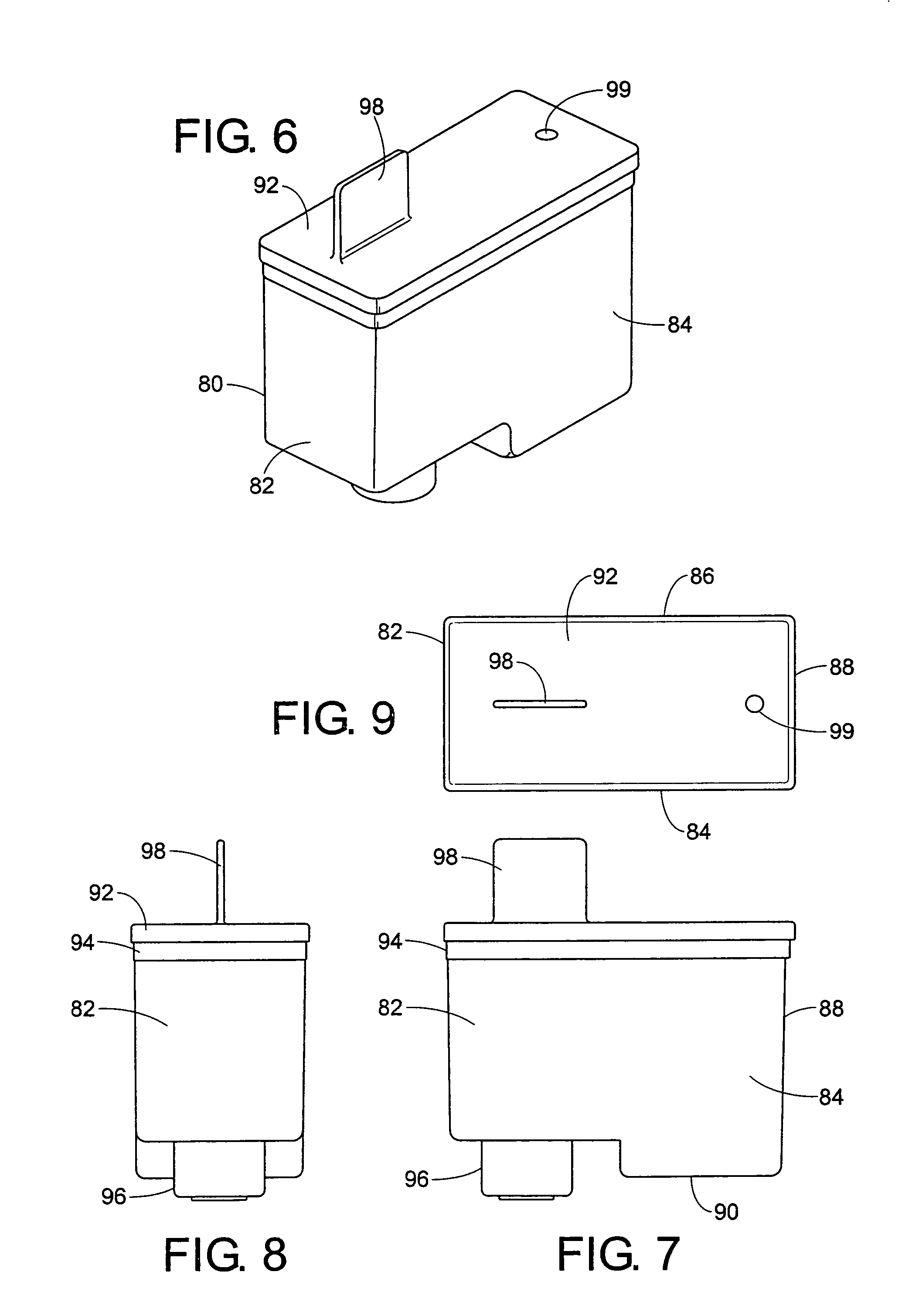
[0038]Referring now to the drawings, wherein the showings are for purposes of illustrating several embodiments of the invention only and not for purposes of limiting same, FIG. 1 shows a prior art ink tank cartridge illustrating the internal structure of the ink cartridge.

[0039]The ink tank cartridge comprises a case or housing 10 which defines an internal cavity of a generally rectangular cross section. The housing has a series of walls including walls 14, 16, and 18 which form an internal cavity 20. An additional dividing wall 22 separates the housing internal cavity into two smaller chambers 24, 26. An opening 30 extends through a lower region of the wall 22 adjacent the bottom wall 18 placing the chambers into communication with each other for ink storage and transfer purposes. Chamber 24 is used to store free ink while chamber 26 is used to store ink in an ink absorbing or porous member 32.

[0040]The ink absorbing member typically comprises a block of porous material or foam suc...


PUM


Abstract

An ink cartridge has a body having a stepped configuration including a first top wall and a second top wall, wherein the second top wall is lower than the first top wall. A lid has a first position selectively secured to the first top wall and a second portion is secured to the second top wall which forms a ledge for removing the cartridge from a printer. Alternately, a tab extends from a surface of the lid for removing the cartridge from a printhead. Another alternative is indentations formed in the lid and side walls of the cartridge for manually gripping the cartridge for removal from a printhead.

Description

BACKGROUND[0001]This application relates generally to the ink-jet printing art for ejecting ink droplets on a recording medium such as paper, and more particularly, to the removal of an ink tank cartridge for use in an ink-jet type recording apparatus such as a printer.[0002]In a conventional recording apparatus, ink is supplied to a recording head from an ink tank constructed as a cartridge. The cartridge can be divided into multiple chambers, where a porous foam or material is positioned over an outlet port in a first chamber and free ink is filled into a second chamber. The free ink migrates from its chamber into the foam through an opening providing communication between the two chambers. The foam then controls the flow of ink as it migrates toward the ink outlet port.[0003]As printers become more compact and smaller, many manufacturers are designing printers which have little space available to easily remove the ink cartridges from the printers by hand. Cartridges typically hav...

Claims


Application Information

Patent Timeline
Patent Type & Authority Patents(United States)
IPC IPC(8): B41J2/175
CPCB41J2/17513B41J2/1755
Inventor LENGYEL, DENNIS MICHAELANDERSON, STEPHEN ABB
Owner NU KOTE INT
Why Eureka
Try Eureka