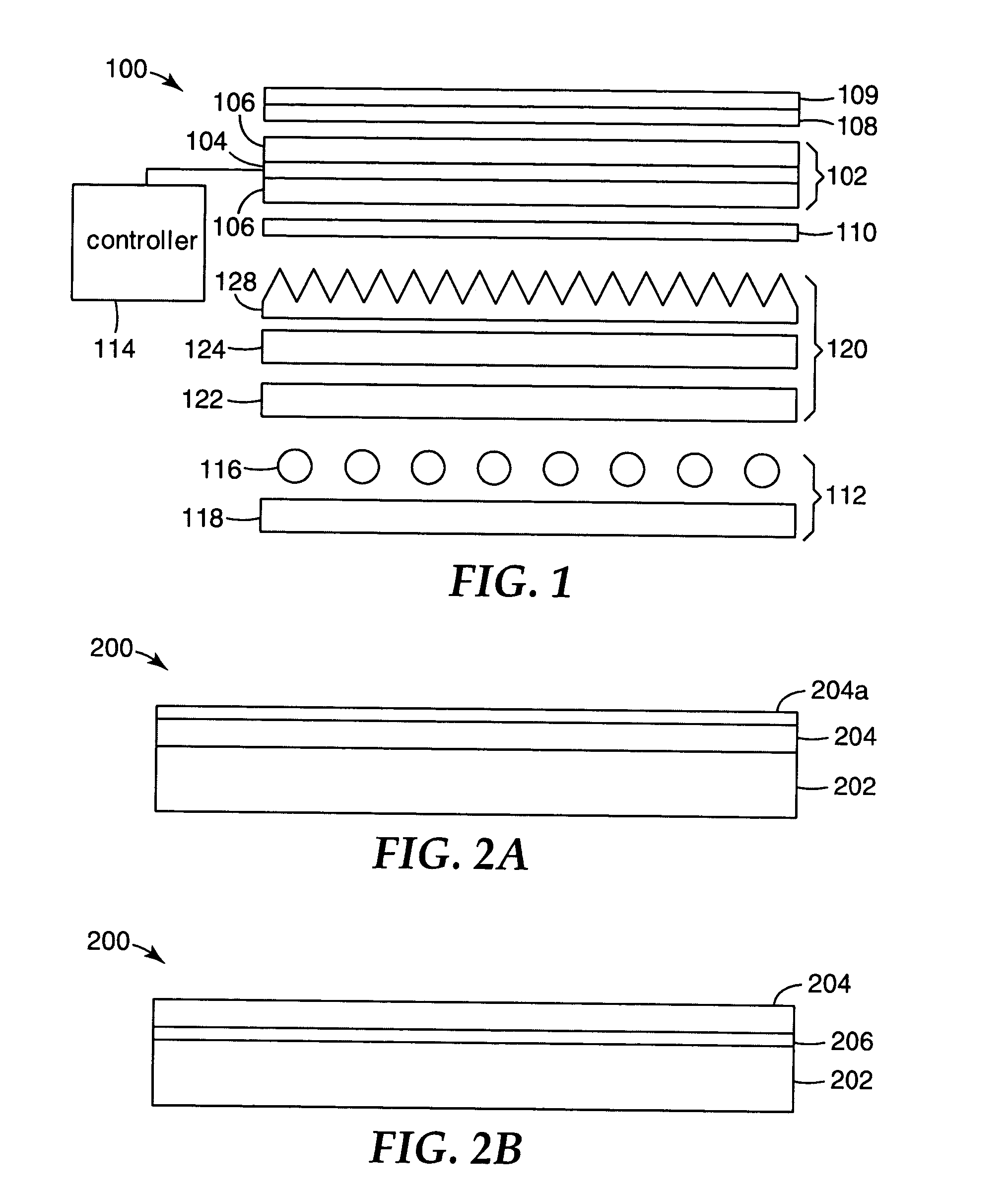
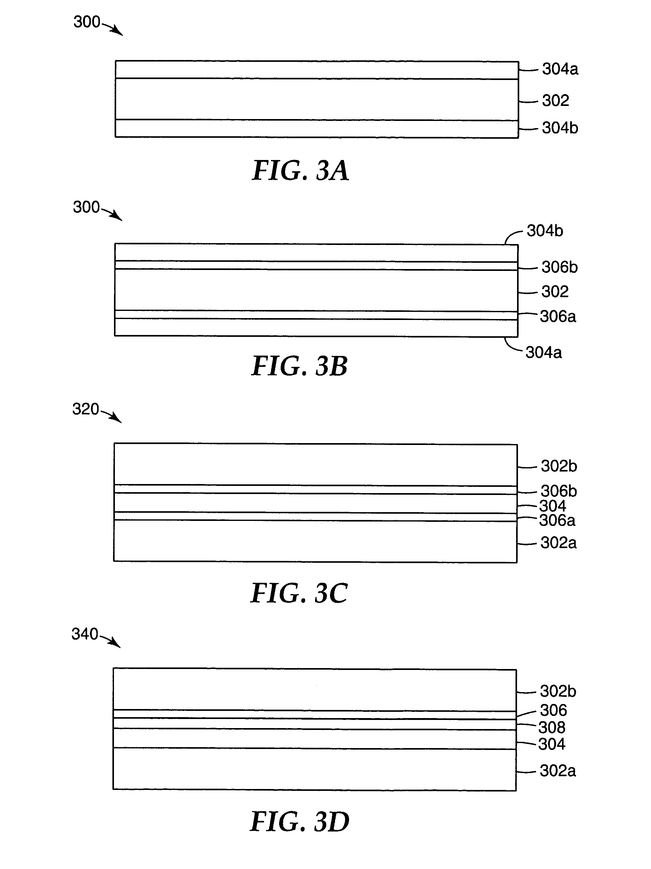
Direct-lit liquid crystal displays with laminated diffuser plates

a technology of diffuser plates and liquid crystal displays, applied in non-linear optics, instruments, optics, etc., can solve the problems of high manufacturing cost, deformation or warpage of plates, and undesirable illumination profiles

Inactive Publication Date: 2008-11-04
3M INNOVATIVE PROPERTIES CO
View PDF50 Cites 47 Cited by
  • Summary
  • Abstract
  • Description
  • Claims
  • Application Information

AI Technical Summary

Problems solved by technology

Such an illumination profile is not desirable, and so a diffuser plate is used to smooth the illumination profile at the back of the LCD device.
These plates often deform or warp after exposure to the elevated temperatures of the lamps.
They are expensive to manufacture, and increase manufacturing costs, since the diffusing pattern must be registered to the illumination source at the time of assembly.
In addition, the diffusion plates require customized extrusion compounding to distribute the diffusing particles uniformly throughout the polymer matrix, which further increases costs.

Method used


Image

  • Direct-lit liquid crystal displays with laminated diffuser plates
  • Direct-lit liquid crystal displays with laminated diffuser plates
  • Direct-lit liquid crystal displays with laminated diffuser plates

Examples


examples

[0088]A number of sample diffuser plates manufactured according to this disclosure were prepared and their performance was compared to that of diffuser plates used in commercially available LCD-TVs. The diffuser plates were tested for single pass light transmission and reflection and for brightness and uniformity.

[0089]Light transmission and reflection measurements of the diffuser plates and substrate materials, for samples S1-S27 and control samples C-1 and C2, were made using a BYK Gardner Haze-Gard Plus instrument, catalog no. 4723 and supplied by BYK Gardner, Silver Spring, Md. The transmission and haze levels were collected according to ASTM-D100-00, titled “Standard Test Method for Haze and Luminous Transmittance for Transparent Plastics”. The instrument was referenced against air during the measurements. In all the measurements for transmission and haze, the D1 side of the diffuser plate was positioned on the same side as the clarity port and the D2 side of the diffuser plate...


PUM

PropertyMeasurementUnit
thickaaaaaaaaaa
thickaaaaaaaaaa
thickaaaaaaaaaa

Abstract

In a directly-illuminated liquid crystal display (LCD), for example an LCD monitor or an LCD-TV, a number of light management films, including a diffuser layer, lie between the light source and the LCD panel to provide bright, uniform illumination. The diffuser layer is attached to a substrate which is separate from the light source and the LCD panel, or may be attached to either the LCD panel or, when using a two dimensional light source, to the light source. The other light management layers may also be attached to the separate substrate or to the LCD panel or two-dimensional light source. High levels of illumination uniformity at the LCD may be achieved with a uniform (non-patterned) diffuser, even with relatively low levels of diffusion, when the diffuser is used with a brightness enhancing layer.

Description

FIELD OF THE INVENTION[0001]The invention relates to optical displays, and more particularly to liquid crystal displays (LCDS) that are directly illuminated by light sources from behind, such as may be used in LCD monitors and LCD televisions.BACKGROUND[0002]Liquid crystal displays (LCDs) are optical displays used in devices such as laptop computers, hand-held calculators, digital watches and televisions. Some LCDs include a light source that is located to the side of the display, with a light guide positioned to guide the light from the light source to the back of the LCD panel. Other LCDs, for example some LCD monitors and LCD televisions (LCD-TVs), are directly illuminated using a number of light sources positioned behind the LCD panel. This arrangement is increasingly common with larger displays, because the light power requirements, to achieve a certain level of display brightness, increase with the square of the display size, whereas the available real estate for locating ligh...

Claims


Application Information

Patent Timeline
Patent Type & Authority Patents(United States)
IPC IPC(8): G02F1/1335
CPCG02F1/133606G02F1/133536G02F1/13362G02F2001/133507G02F2001/133607G02F2201/086G02F1/133507G02F1/133607
Inventor KO, BYUNGSOOGEHLSEN, MARK D.CHEN, CHINGWENEMMONS, ROBERT M.LAUMER, JAMES W.KIM, JI-HYUNGLEE, JI-HWASEO, KANG-ILFABICK, RYAN T.RIVARD, LINDA M.EPSTEIN, KENNETH A.KIM, CHIDEUKPARK, YOUNGSOO
Owner 3M INNOVATIVE PROPERTIES CO
Why Eureka
Try Eureka