Clutch cooling grooves for uniform plate temperature in friction launch

a technology of friction launch and cooling groove, which is applied in the direction of fluid actuated clutches, clutches, non-mechanical actuated clutches, etc., can solve the problems of unsatisfactory high temperatures, damage to steel and friction materials, and breakdown of cooling fluid base stock and additives, so as to reduce temperatures and minimize heat distortion of steel disks

Inactive Publication Date: 2008-11-11
GM GLOBAL TECH OPERATIONS LLC
View PDF9 Cites 7 Cited by
  • Summary
  • Abstract
  • Description
  • Claims
  • Application Information

AI Technical Summary

Benefits of technology

[0005]The present invention reduces the maximum temperature of the steel disks in a clutch, particularly at the interfaces between the steel disks and the friction material, by varying the shape of cooling grooves formed in friction plates, juxtaposed to the steel disks. The present invention also provides a method of maintaining uniform or near-uniform temperatures in the steel plates near the interfaces between the steel disks and the friction material by varying the shape of the cooling grooves. Reduced temperatures in the steel disks are beneficial for durability and functionality reasons. Primarily, reduced temperatures minimize heat distortion of the steel disks and oxidation of fluid and friction material.
[0007]To maintain near-constant temperatures in the steel disks at the interfaces between the steel disks and the friction material (the disk-friction material interfaces), the cross-sectional area of each groove is increased in areas where the steel disk temperatures would be above average if the cross-sectional area were not increased. The cross-sectional area of each groove is, thus, smallest at the cooling fluid inlet, where the cooling fluid is the coolest and the disk peripheral edge has area that is not covered with friction material and is exposed to the cooling fluid; wider at the cooling fluid outlet, where the cooling fluid is hottest and the disk peripheral edge has area that is not covered with friction material and is exposed to the cooling fluid; and widest adjacent the hot areas in the steel disks, where the cooling fluid is hotter than at the fluid inlet but cooler than at the cooling fluid outlet and there is no disk peripheral edge to enhance cooling. Any groove shape that has the smallest cross-sectional area at the cooling fluid inlet and the largest cross-sectional area in the area between the cooling fluid inlet and the cooling fluid outlet is within the scope of the present invention and can be further adapted to increase its efficiency by other factors, such as minimizing the distance from the center of the friction material to the grooves to allow for more heat transfer from the steel disk to the cooling fluid.
[0008]The present invention includes a friction plate adapted for use in a clutch assembly. The friction plate is utilized in association with a steel disk having a disk inner peripheral edge, a disk outer peripheral edge, and a disk facing surface. The friction plate has a friction plate facing surface juxtaposed with the disk facing surface. The friction plate facing surface has a plurality of grooves formed to carry cooling fluid from one of the friction plate inner peripheral edge and the friction plate outer peripheral edge to the other of the friction plate inner peripheral edge and the friction plate outer peripheral edge. The grooves are formed to enhance cooling of the steel disk. Each groove has a groove inlet cross-sectional area, a groove central cross-sectional area, and a groove outlet cross-sectional area. The groove outlet cross-sectional area is larger than the groove inlet cross-sectional area and the groove central cross-sectional area is larger than the groove outlet cross-sectional area. This groove shape provides that the largest cross-sectional area of each groove is adjacent to what would otherwise be a hot area of the steel disk, which has the effect of reducing the temperature at the hot area. Thus, the amount of heat transferred from the expected hot areas into the cooling fluid is substantially greater than the amount of heat transferred at other locations along the grooves into the cooling fluid.
[0010]The present invention provides a clutch assembly comprised of a friction plate with a friction plate facing surface juxtaposed with a disk facing surface of a steel disk. The steel disk has a disk inner peripheral edge and a disk outer peripheral edge. The friction plate facing surface has a plurality of grooves formed therein to carry cooling fluid from one of the friction plate inner peripheral edge and the friction plate outer peripheral edge to the other of the friction plate inner peripheral edge and the friction plate outer peripheral edge. The grooves are formed to enhance cooling of the steel disk. The grooves have a groove shape such that the grooves have the largest groove cross-sectional area adjacent to what would be a hot area of the steel disk if the groove area was constant. Each groove may have one or more branches for the cooling fluid to flow. Additionally, each groove may have two or more openings to the friction plate inner peripheral edge and / or the friction plate outer peripheral edge.

Problems solved by technology

Insufficient cooling can result in undesirably high temperatures in the steel disk and in the cooling fluid, which may cause damage to the steel and friction material.
It may also cause a break down of the base stock and additives in the cooling fluid.
Improper cooling in the steel disk can cause localized hot areas or “hot spots,” which may result in distortion and damage to the steel disk and the friction material.
Damage at the disk-friction material interface can adversely affect durability or function.
The types of damage affecting durability include “burned” friction material, distorted steel plates, oxidized oil, and additive depletion in oil.
The types of damage affecting functionality include changes in friction characteristics near the hot area that can lead to shudder and rapid reduction in torque capacity.
A hot area can cause damage to the steel disk, the friction material, and the cooling fluid even if the average temperature of the material is within acceptable limits.

Method used


Image

  • Clutch cooling grooves for uniform plate temperature in friction launch
  • Clutch cooling grooves for uniform plate temperature in friction launch
  • Clutch cooling grooves for uniform plate temperature in friction launch

Examples


Embodiment Construction

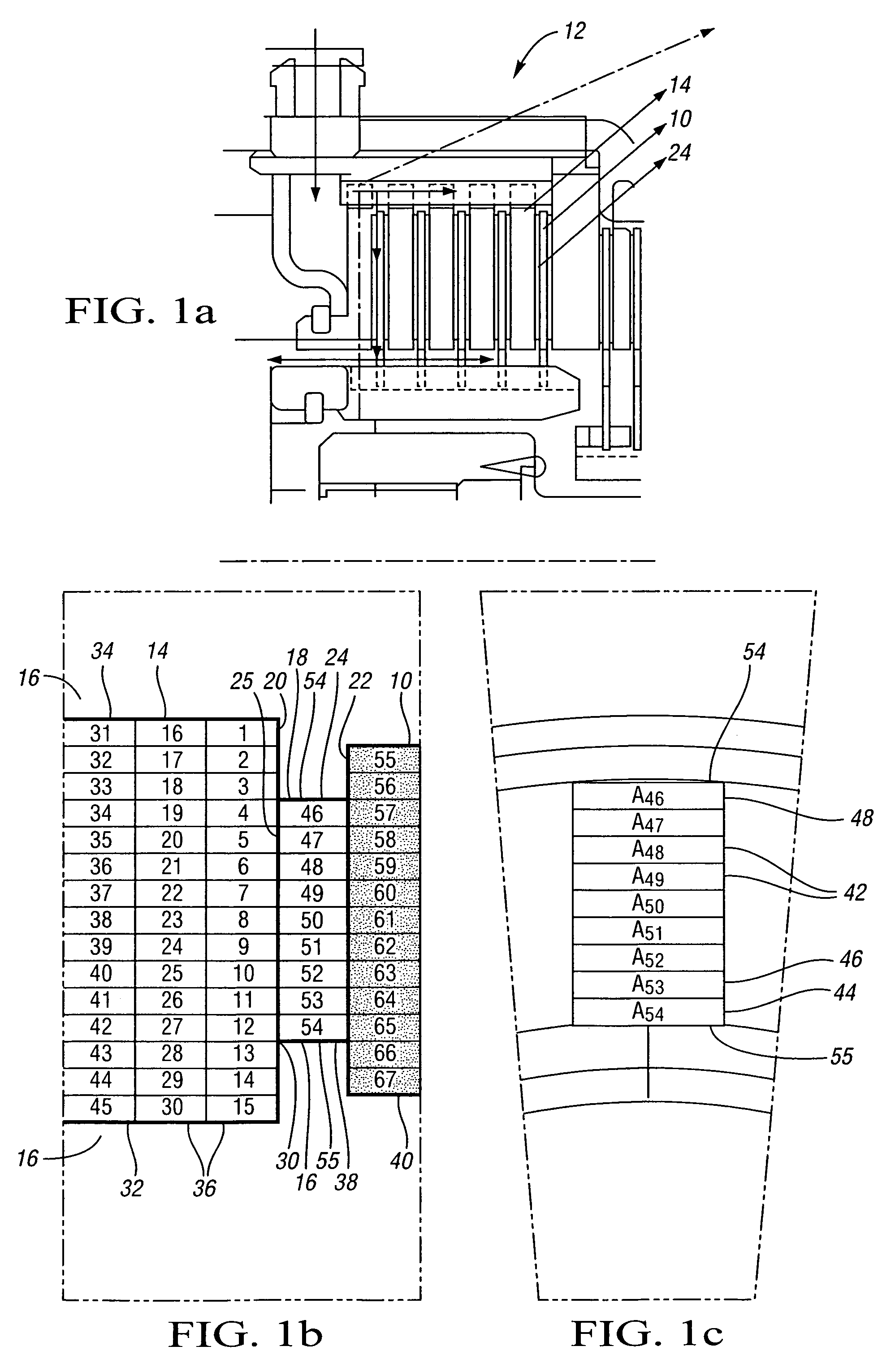
[0027]An example of clutch reaction plates with cooling flow paths is described in published U.S. patent application Ser. No. 10 / 366,911 (U.S. Patent Publication No. 2004-0159519), filed on Feb. 14, 2003, assigned to General Motors Corporation, and hereby incorporated by reference in its entirety.

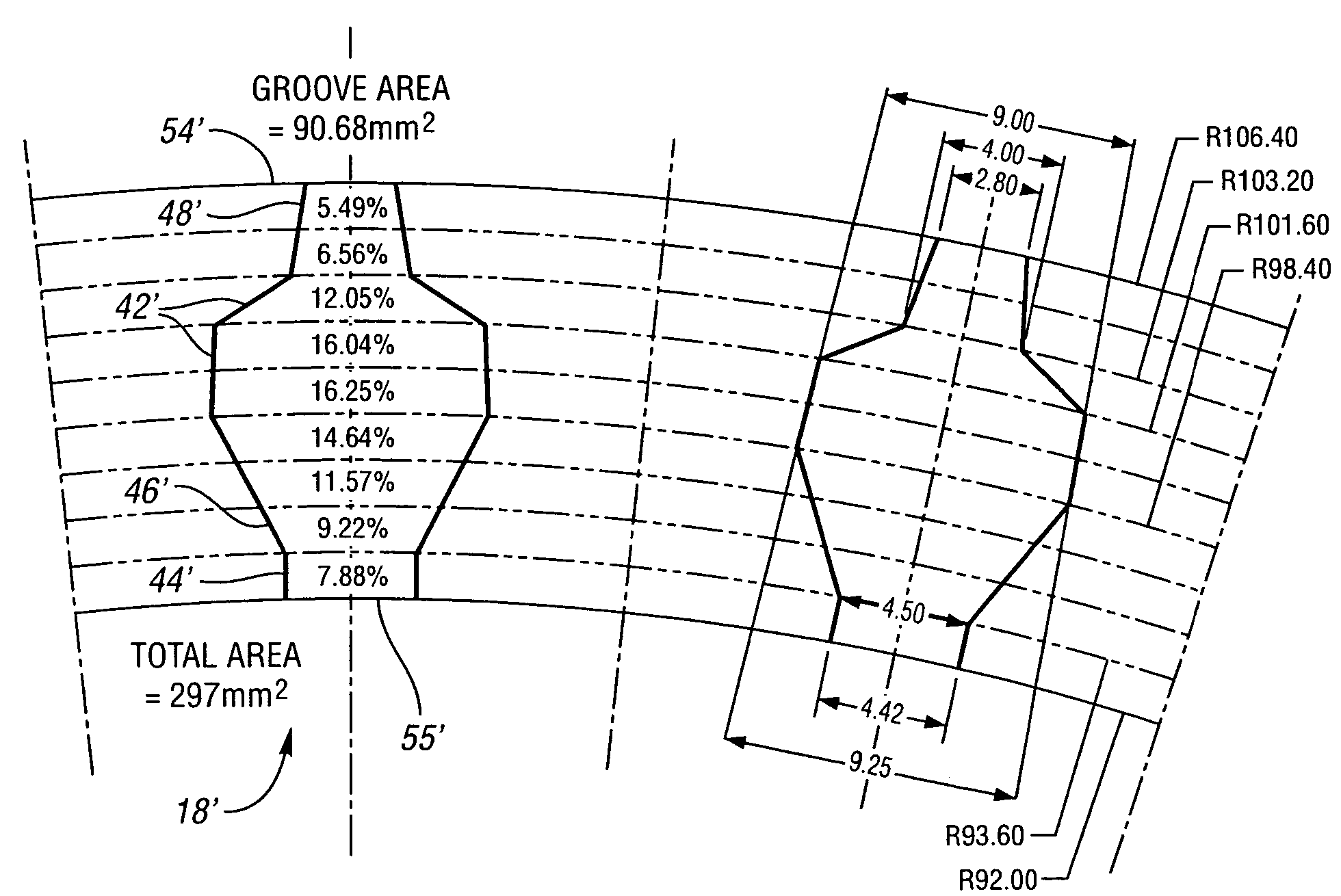
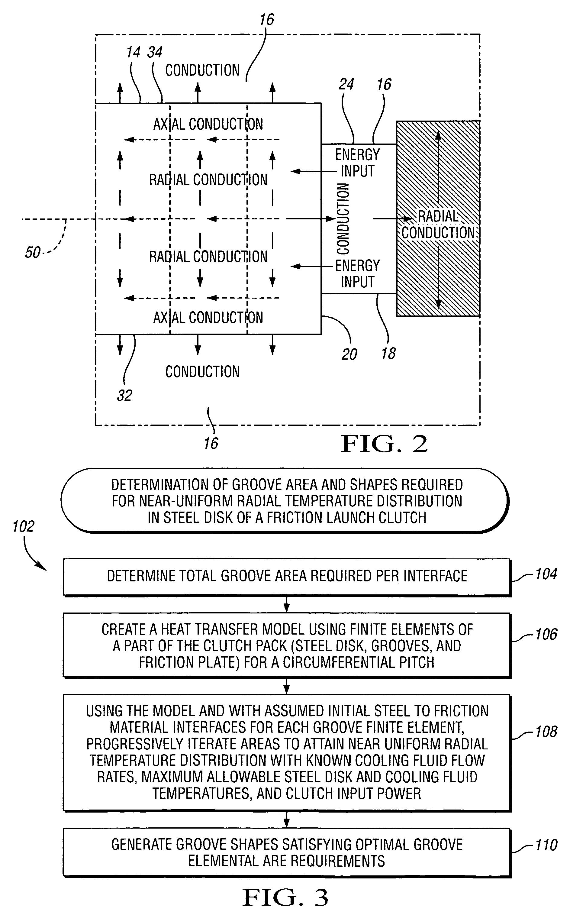
[0028]Referring to the drawings, FIGS. 1a, 1b, and 1c are diagrammatic representations of a clutch 12, which includes steel disks 14, cooling fluid 16, friction plates 10 such as 10′, 10″, 10′″, 10″″, and friction material 24. The steel disks 14 have a disk facing surface 20 juxtaposed with the friction plate facing surface 22 of the friction plates 10. The friction plate facing surface 22 is at least partially faced with friction material 24. Heat is generated along the disk-friction material interface 30 while the clutch 12 is slipping with friction between the disk facing surface 20 and the friction material facing surface 25 of the friction material 24, which is in contact with the disk...


PUM


Abstract

Clutch cooling grooves formed on a friction plate are provided. The grooves are shaped to provide for substantially uniform steel disk temperatures in friction launch of a vehicle. The grooves are shaped such that the largest cross-sectional area is located adjacent to what would otherwise have been a hot area on the steel disk and the smallest cross-sectional area is located at the coolest location on the steel disk, at the cooling fluid inlet. Thus, the groove is shaped such that the smallest cross-sectional area is located at the cooling fluid inlet, the largest cross-sectional area is located between the cooling fluid inlet and the cooling fluid outlet, and the cooling fluid outlet has a cross-sectional area larger than the cooling fluid inlet and smaller than the cross-sectional area adjacent to the hot spot of the steel disk, between the cooling fluid inlet and the cooling fluid outlet.

Description

CROSS REFERENCE TO RELATED APPLICATIONS[0001]This application claims the benefit of U.S. Provisional Application No. 60 / 582,865 filed Jun. 25, 2004, which is hereby incorporated by reference in its entirety.TECHNICAL FIELD[0002]The invention relates to clutch cooling grooves in a friction launch clutch.BACKGROUND OF THE INVENTION[0003]An integrated friction launch clutch may be used instead of a torque converter as a coupling device in an automatic transmission during the vehicle launch process. A launch clutch usually comprises a pack of steel disks splined to a housing and friction plates splined to a hub, arranged alternately to provide disk-plate contact interfaces. The friction plates are comprised of a thin plate with friction material, segmented or un-segmented, attached on at least one side of the friction plate. A piston applies the clutch during vehicle launch. A launch clutch is slipped for a longer time than a shifting clutch. Thus, the heat generated in a launch clutch ...

Claims


Application Information

Patent Timeline
Patent Type & Authority Patents(United States)
IPC IPC(8): F16D13/72F16D13/64F16D25/12F16D69/00
CPCF16D13/648F16D13/72F16D25/123F16D2069/004
Inventor ARCOT, MURALI KRISHNAN S.STEVENSON, PAUL D.
Owner GM GLOBAL TECH OPERATIONS LLC
Why Eureka
Try Eureka