Surface illuminator and liquid crystal display having the same

a technology of liquid crystal display and surface illuminator, which is applied in the direction of non-linear optics, lighting and heating apparatus, instruments, etc., can solve the problems of increased device size to accommodate radiation fins, low light utilization, and increased cost attributed to increased leds used. , to achieve the effect of high display quality

Inactive Publication Date: 2008-11-11
SHARP KK
View PDF9 Cites 13 Cited by
  • Summary
  • Abstract
  • Description
  • Claims
  • Application Information

AI Technical Summary

Benefits of technology

[0015]It is an object of the invention to provide a surface illuminator which employs an array of discrete light sources to provide high display quality and a liquid crystal display having the same.
[0017]The invention makes it possible to provide a surface illuminator employing an array of discrete light sources to provide high display quality and a liquid crystal display having the same.

Problems solved by technology

There is a problem in that the system as a whole results in very low utilization of light because light enters the sub light guide from LEDs and enters the sub light guide from the main light guide at low efficiency.
Since the low utilization of light necessitates an increase in the power supplied and consequently necessitates countermeasures against heat, a problem also arises in that the size of a device is increased to accommodate a radiation fin.
Another problem arises in that there is a cost increase attributable to an increase in the number of LEDs used.
As a result, mixed white that lacks a red component is generated at the arbitrary point P1, and a problem therefore arises in that a color irregularity is liable to occur in the neighborhood of the top end of the reflective surface 113L.
The same problem occurs even if the LED sets 100 have a “GRGB” pattern instead of the “GBGR” pattern.

Method used


Image

  • Surface illuminator and liquid crystal display having the same
  • Surface illuminator and liquid crystal display having the same
  • Surface illuminator and liquid crystal display having the same

Examples


first embodiment

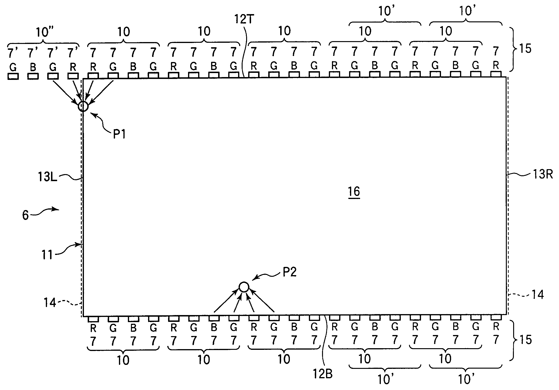
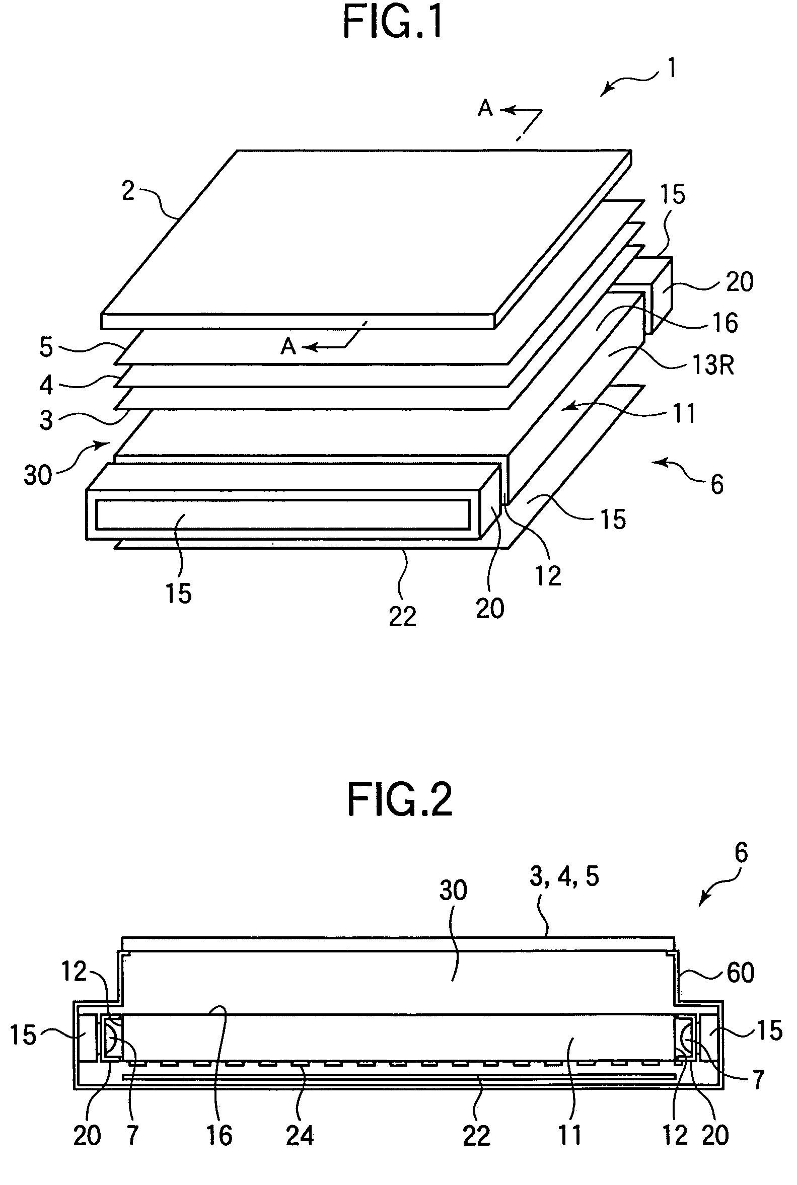
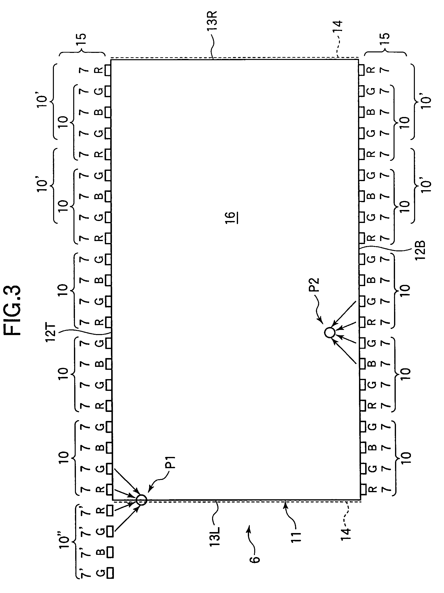
[0024]A description will now be made with reference to FIGS. 1 to 3 on a surface illuminator employing an array of discrete light sources and a liquid crystal display having the same according to a first embodiment of the invention. FIG. 1 is an exploded perspective view showing a schematic structure of a liquid crystal display 1 having a backlight unit as a surface illuminator according to the present embodiment. FIG. 2 is a view of a main structure of the backlight unit 6 of the liquid crystal display shown in FIG. 1 taken along the line A-A. As shown in FIGS. 1 and 2, the liquid crystal display 1 of the present embodiment includes a liquid crystal display panel 2 provided by sealing a liquid crystal between a pair of substrates and the backlight unit 6 which is a surface illuminator.

[0025]The backlight unit 6 includes a light guide 11 which is constituted by, for example, a transparent member in the form of a rectangular thin plate having a predetermined thickness. The light guid...

second embodiment

[0043]A description will now be made with reference to FIG. 4 on a surface illuminator employing an array of discrete light sources and a liquid crystal display having the same according to a second embodiment of the invention. A surface illuminator 6 of the present embodiment is similar in configuration to the surface illuminator 6 in the first embodiment, and it has a configuration according to the first embodiment as shown in FIGS. 1 and 2. Therefore, elements identical to those in the first embodiment in operations and effects will be indicated by like reference numerals, and the description thereof will be omitted.

[0044]FIG. 4 shows a positional relationship between a light exit surface 16 of a light guide 11 of the backlight unit 6 and LED light sources 15 in the present embodiment in a view of the unit taken in a direction normal to the light exit surface 16. The present embodiment is different from the first embodiment in that it is characterized by R (red) emission LEDs 8R ...

third embodiment

[0048]A description will now be made with reference to FIG. 5 on a surface illuminator employing an array of discrete light sources and a liquid crystal display having the same according to a third embodiment of the invention. A surface illuminator 6 of the present embodiment is similar in configuration to the surface illuminator 6 in the first embodiment, and it has a configuration according to the first embodiment as shown in FIGS. 1 and 2. Therefore, elements identical to those in the first embodiment in operations and effects will be indicated by like reference numerals, and the description thereof will be omitted.

[0049]FIG. 5 shows a positional relationship between a light exit surface 16 of a light guide 11 of the backlight unit 6 and LED light sources 15 in the present embodiment in a view of the unit taken in a direction normal to the light exit surface 16. The present embodiment is different from the first embodiment in that a part of light emitted by LEDs 7R serving as end...


PUM

PropertyMeasurementUnit
sizesaaaaaaaaaa
widthaaaaaaaaaa
widthaaaaaaaaaa

Abstract

The invention relates to a surface illuminator and a liquid crystal display having the same and provides a surface illuminator capable of achieving high display quality by employing an array of discrete light sources and a liquid crystal display having the same. A reflective surface for reflecting light in a light guide region of a light guide extends from an end of a light entrance surface through which light enters the light guide region. An LED light source serving as an array of discrete light source is constituted by a red emission LED, a green emission LED, a blue emission LED, and another green emission LED provide alternately and discretely along the light entrance surface. A red LED serving as an end light source provided at the end of the LED light source on the side of an end of a reflective surface is disposed such that about one half of an emitting region of the same is obscured by the reflective surface to prevent about one half of the quantity of light emitted from entering the light guide region.

Description

BACKGROUND OF THE INVENTION[0001]1. Field of the Invention[0002]The present invention relates to a surface illuminator utilizing an array of discrete light sources and a liquid crystal display having the same.[0003]2. Description of the Related Art[0004]A liquid crystal display is provided with a surface illuminator on a front side or back side of a liquid crystal display panel thereof. Backlight units which are surface illuminators disposed on the back side of a panel include side light (edge light) types including a light source disposed along a side edge of a light guide for guiding light and direct types including a light source disposed directly under a liquid crystal display panel. Referring to the use of those types of illuminators in general, side light type backlight units are used in liquid crystal displays having screen sizes of 20 (20 inches in the diagonal direction) or less and liquid crystal displays which must have an especially small thickness. While either type of ...

Claims


Application Information

Patent Timeline
Patent Type & Authority Patents(United States)
IPC IPC(8): F21V7/04F21V9/00F21S2/00F21V8/00F21Y101/02G02B6/00G02F1/13357
CPCG02B6/0043G02B6/0068G02B6/00G02B6/0001G02F1/133
Inventor SUZUKI, TOSHIHIRO
Owner SHARP KK
Why Eureka
Try Eureka