Handle assembly

a technology of routers and handles, applied in the field of power tools, can solve the problems of user's hand becoming more easily fatigued, and user's grasping of the router's motor housing experiencing fatigu

Inactive Publication Date: 2008-11-18
BLACK & DECKER INC
View PDF165 Cites 27 Cited by
  • Summary
  • Abstract
  • Description
  • Claims
  • Application Information

AI Technical Summary

Problems solved by technology

In either case, these handles may not meet user demands.
A drawback to grasping the main body of the router, such as the motor housing and the base, is that a user's hand may become more easily fatigued.
For instance, a user grasping a router's motor housing may experience fatigue because he / she may tend to hold up his / her arm at an awkward angle or force their hand into an uncomfortable position.

Method used


Image

  • Handle assembly
  • Handle assembly
  • Handle assembly

Examples


Embodiment Construction

[0026]Reference will now be made in detail to the presently preferred embodiments of the invention, examples of which are illustrated in the accompanying drawings. Those of skill in the art will appreciate that the apparatus of the present invention may be implemented with various power tools such as a dedicated plunge router and a removable base plunge router without departing from the spirit and scope of the present invention.

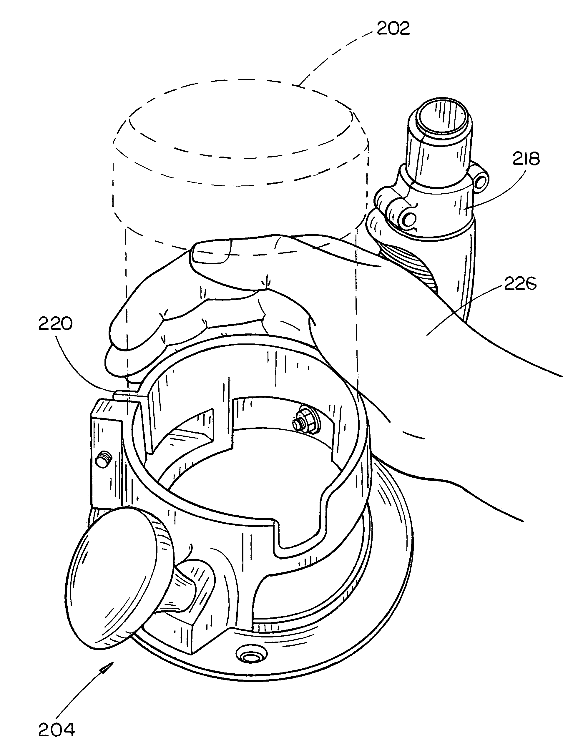
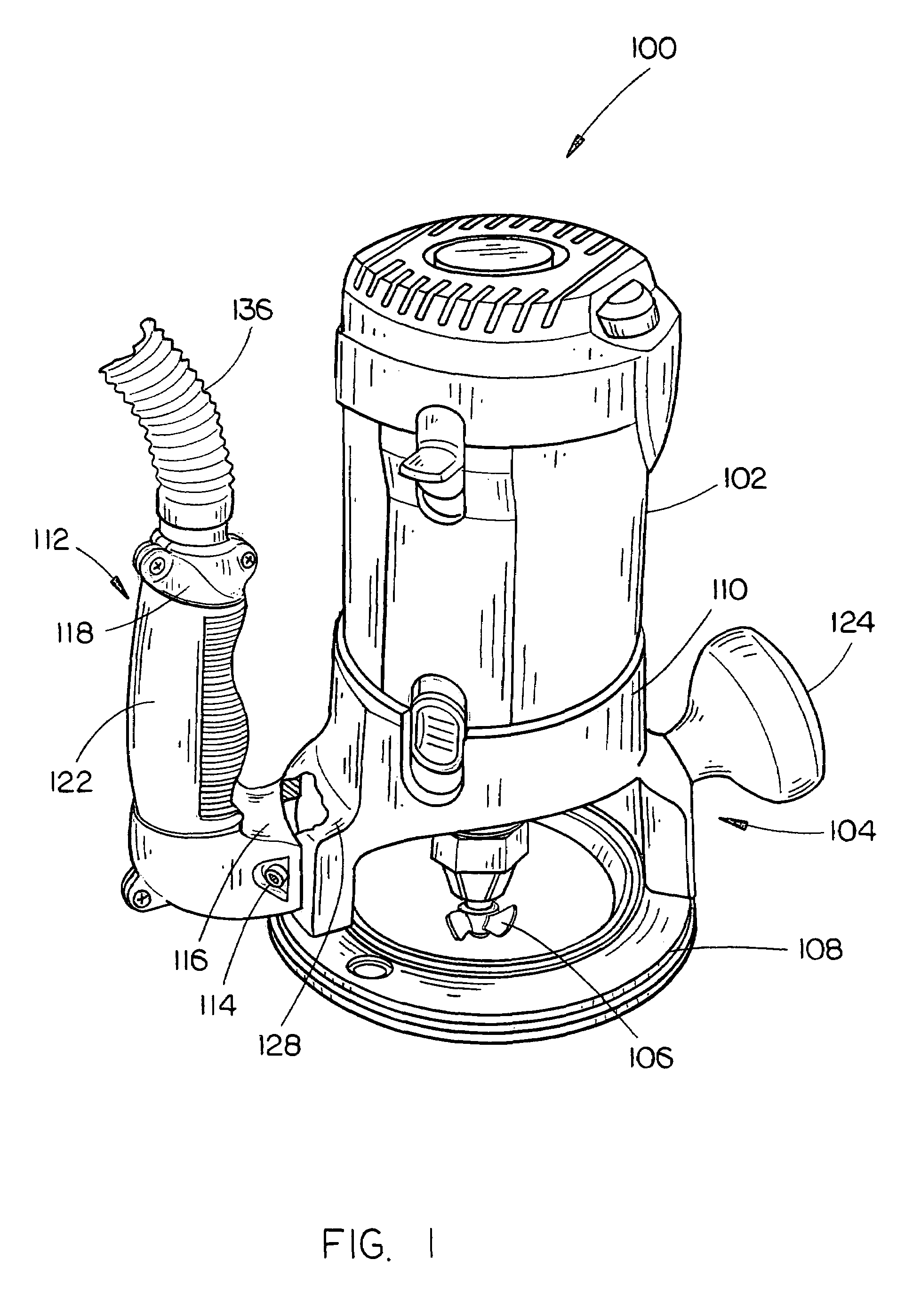
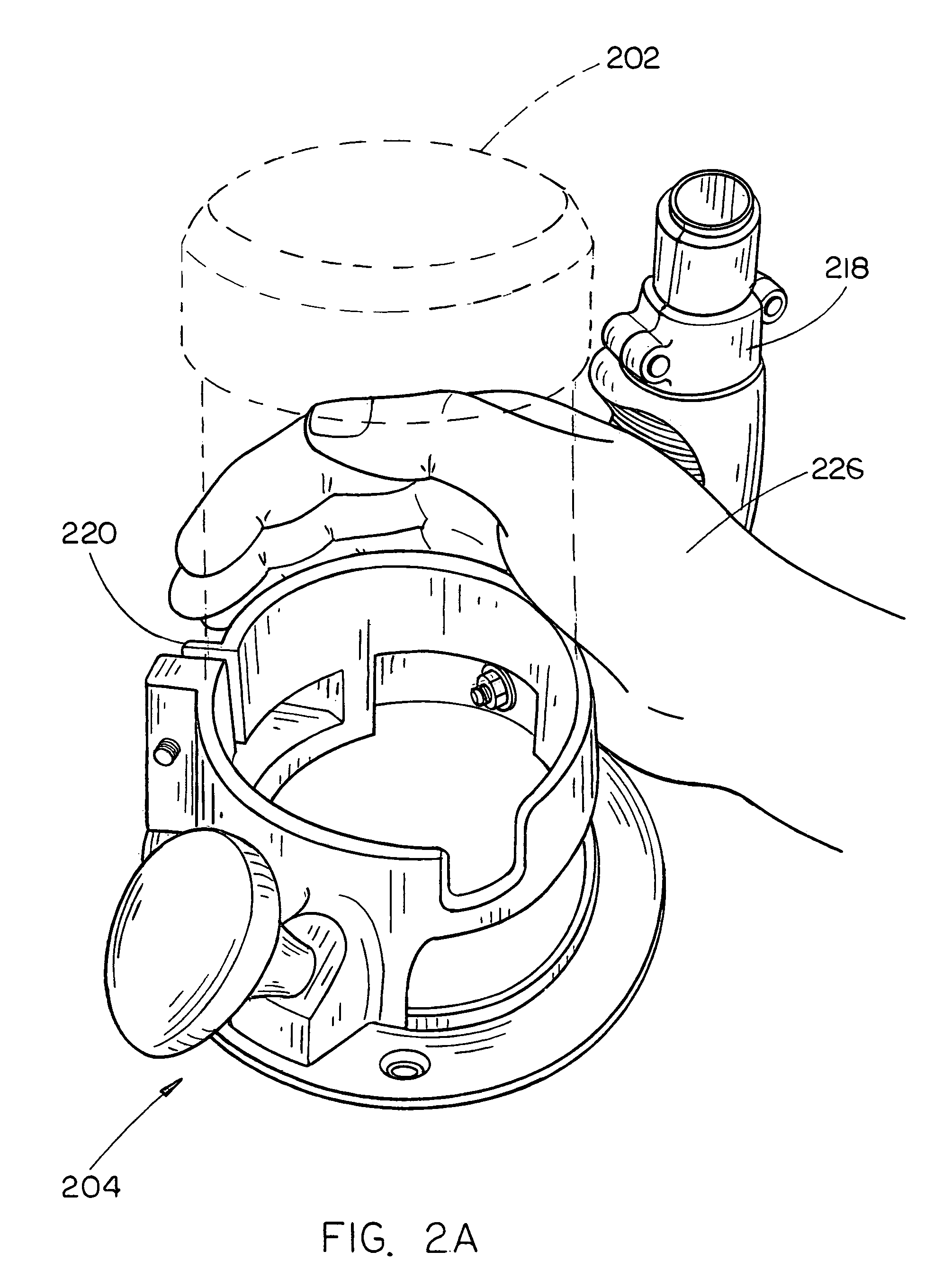
[0027]Referring to FIG. 1, a router 100 in accordance with an exemplary embodiment of the present invention is described. In the present example, the router 100 is a standard or fixed base type router in which the motor housing 102 is removable from a base 104. The base 104 is configured to at least partially support the router 100 on a support surface or a workpiece. For instance, a user may support the router on a portion of the base while shaping a panel edge. When utilizing a fixed base router, the user adjusts the position of the motor housing 102 so tha...


PUM

PropertyMeasurementUnit
angleaaaaaaaaaa
θ (theta)aaaaaaaaaa
θ (theta)aaaaaaaaaa

Abstract

The present invention is directed to an apparatus for providing convenient grasping of a router adjacent base / motor housing includes a base for supporting a motor housing for driving a working tool. A generally L-shaped handle including a connecting member and grasping member is connected to the base for permitting a user to comfortably manipulate the power tool adjacent the motor housing. In further aspect, a removable a generally L-shaped handle includes a channel extending through the handle for directing dust and debris away from the working tool.

Description

CROSS REFERENCE[0001]The present application is a Continuation-in-Part and claims priority under 35 U.S.C. §120 to U.S. patent application Ser. No. 10 / 686,300, entitled Quick Release Sub-Base Router, filed on Oct. 15, 2003, which in-turn claims priority under 35 U.S.C. §119(e) to U.S. Provisional Patent Ser. No. 60 / 418,510, entitled: Router, filed on Oct. 15, 2002, and U.S. Provisional Patent Ser. No. 60 / 467,169, entitled: Router, filed on May 1, 2003 all of which are hereby incorporated by reference in their entirety.[0002]The instant application hereby incorporates U.S. patent application Ser. No. 10 / 384,510, entitled Router Base Securing Mechanism, filed on Mar. 3, 2003 and U.S. patent application Ser. No. 10 / 458,167, entitled: Switch Assembly, filed on Jun. 10, 2003 by reference in their entirety.FIELD OF THE INVENTION[0003]The present invention generally relates to the field of power tools and more particularly to a handle assembly for a router.BACKGROUND OF THE INVENTION[0004]...

Claims


Application Information

Patent Timeline
Patent Type & Authority Patents(United States)
IPC IPC(8): B27C5/10
CPCB25F5/02B27C5/10Y10T409/306608Y10T409/304088
Inventor COOPER, RANDY G.ETTER, MARK A.GRIFFIN, GREG K.ALLEN, GINGER L.KILBOURNE, DERRICKLEASURE, JEREMY D.
Owner BLACK & DECKER INC
Why Eureka
Try Eureka