Eyeframe with interchangeable lenspieces held by magnetic closure and interchangeable lens system

a technology of interchangeable lenses and eye frames, which is applied in the field of eyeglasses with, can solve the problems of cumbersome and difficult insertion and removal of lenses, high manufacturing cost, and high cos

Inactive Publication Date: 2008-11-18
LIPAWSKY STEVEN R
View PDF19 Cites 37 Cited by
  • Summary
  • Abstract
  • Description
  • Claims
  • Application Information

AI Technical Summary

Benefits of technology

[0027]With the foregoing and other objects in view there is provided, in accordance with the invention, an eyeframe for use with interchangeable lenspieces, i.e. interchangeable lenses and any surrounding rimwire. The eyeframe includes a rimwire and a closure. The closure is held magnetically closed. Interchangeable eyeglass lenses can be slid between the rimwire and the closure. The closure prevents the interchangeable lenses from unintentionally separating from the eyeframe. In an opened position, the closure allows the removal and interchanging of lenses. In a closed position, the closure prevents the lenses from being removed from the eyeframe. Because the closure is magnetic, the closure does not wear down with use. In addition, unlike mechanical snap closures, the magnetic closure according to the invention is operable with only enough force to overcome the magnets and (i.e. opened and closed) without the force that could crack the lenses.
[0035]To help support the lenses on the eyeframe, at least one prong can be attached to each lens frame to provide stability and balance. The auxiliary clip helps to support the interchangeable lenspiece on the eyeframe and provide balance and stability. A prong is soldered onto each temple of the interchangeable lenspiece. The prong abuts the stem of the eyeframe. If a rimlock is present, the prong can rest on the rimlock.
[0036]The nose bridge of the eyeframe and the nose bridge of the interchangeable lenspiece can include a pawl that mates with a respective slot. The pawl may be on the interchangeable lenspiece and the slot on the eyeframe, or vice versa. By making the pawl and slot any shape but round, the interchangeable lenspiece is prevented from rotating relative to the eyeframe.
[0039]The invention provides a set of eyeglasses that can include lenses that are preferred or required for an occupation. The same frames can then be reused with different lenses for recreational use. By being usable for both occupational and recreational uses, the wearer can save the expense of having to buy two frames. Because the wearer only needs to buy one frame, instead of multiple frames, the wearer may be encouraged to pay more for the multiple-use frame.
[0041]In accordance with a further object of the invention, the magnetic closure includes a slot and a pawl that seats in the slot to help the closure lock with the bridge. In particular, a slot can be formed in the nose bridge or the closure nose bride. A pawl that fits in the slot is placed in the other of the nose bridge or the closure nose bridge. The inclusion of a slot and pawl allows the closure to mechanically seat within the closure. This type of slot and pawl mechanical closure when combined with a magnetically closed bridge creates a very strong closure. Unlike purely magnetic closures, a magnetic-mechanical closure using a slot and pawl as well as magnets is wiggle free and prevents the bridge from moving slightly which can allow the interchangeable lens to jiggle.
[0046]In accordance with a further object of the invention, the magnetic fasteners can be connected to the eyeframe, in particular the nose bridge, and to the closure. The magnetic fasteners may be cemented, welded, soldered, forged, or glued to the frame. This method of connecting the magnetic fastener is the least expensive but results in the magnetic fastener being visible when the closure is in an opened position.

Problems solved by technology

Exchangeable lens eyeglasses have been known for some time but older configurations have had significant shortcomings in that they are generally mechanically complex, making them expensive to manufacture.
Other configurations require substantial mutual deformation of the lens and the front component of the frame making insertion and removal of a lens cumbersome and difficult.
The eyeglasses shown in this patent have met with widespread success but they are relatively expensive due to the complete wire front, which is typically formed of a wire stock, and must be soldered in a separate manufacturing step to form a closed loop.
Also, a complete wire rim is limited in its ability to accommodate designer materials and colors.
Complete wire rims, especially those for mating with exchangeable lenses can present a problem in that the wire rims are susceptible to bending or other deformation, which destroys the relatively close-tolerance lens-conforming configuration.
Also, the lenses themselves are unsupported during storage.
Plastic and polycarbonate lenses may tend to warp if stored under conditions of excessive heat or pressure and can also scratch relatively easily.
While generally satisfactory, the eyeglasses shown in this patent present some difficulties for wearers who have limited manual dexterity or who are engaged in outdoor winter sports or other activities requiring gloves.
This interchangeable eyeglass configuration has considerable mass (i.e. bulk) and is therefore relatively heavy.
This configuration relies on frictional engagement between the wire and plastic bridges, which are susceptible to wear over years of use.
To compensate for this wear, the temple pieces can be adjusted to increase pressure on the wearer's ear, thereby pressing the bridge portions together, but this may be uncomfortable over extended wearing times.
Eventually mechanical clasps wear to the point of not locking.
This leads to the interchangeable lens not being locked in the eyeglasses allowing it to unintentionally fall out.
Another problem with mechanical claps is that they require physical force to lock and unlock them.
For a secure hold, the amount of force may be enough to crack or chip the lens if the force is accidentally transferred to the lens.
Accordingly, a clumsy effort to lock or unlock the bridge could lead to enough force to damage the lens to be brought onto lens.
The mechanical closure is subject to wear and, as the retaining clip become permanently deformed, the retaining clip will fail to retain the lenses.
Prior-art examples that include magnets fail to hide the magnets.
These magnets, when visible, disturb the aesthetic norm of eyeglass frames that typically have no magnets visible.

Method used


Image

  • Eyeframe with interchangeable lenspieces held by magnetic closure and interchangeable lens system
  • Eyeframe with interchangeable lenspieces held by magnetic closure and interchangeable lens system
  • Eyeframe with interchangeable lenspieces held by magnetic closure and interchangeable lens system

Examples


Embodiment Construction

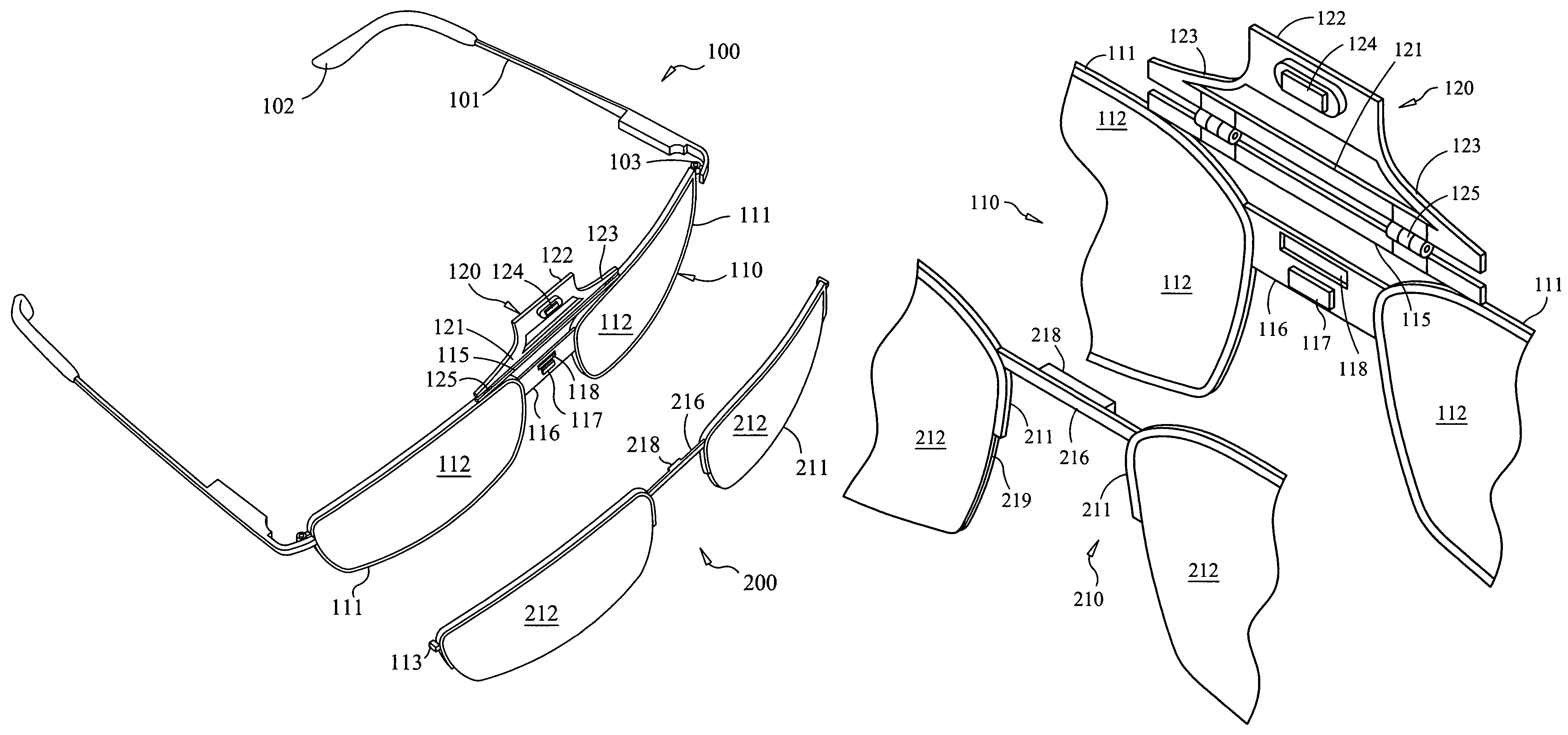
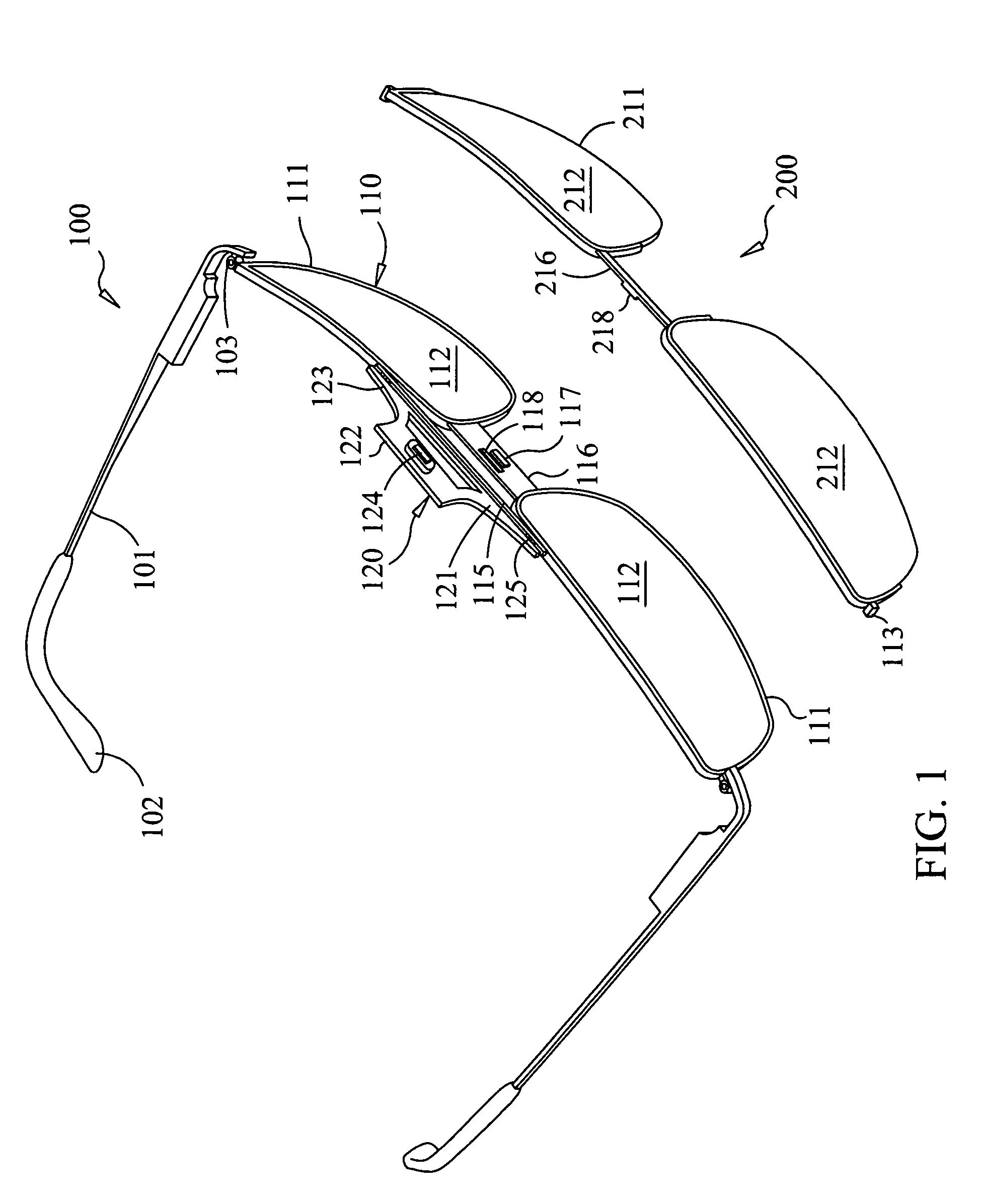
[0062]Referring now to the figures of the drawing in detail and first, particularly, to FIG. 1 thereof, there is seen an eyeframe that is generally marked with reference number 100. Like most eyeframes, the eyeframe 100 includes two stems 101. Each stem 101 has an earpad 102. Each stem 101 connects to a common rimwire 110 at a stem hinge 103.

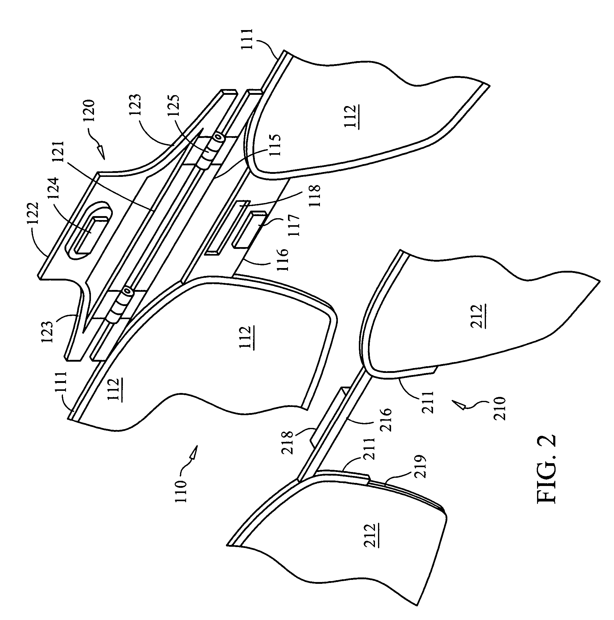
[0063]The rimwire 110 is the front part of the eyeframe 100. The rimwire 110 forms two loops, which are lens frames 111. The lens frames 111 roughly overly a wearer's eye sockets when worn. The lens frames 111 are interconnected by a nose bridge 116. The nose bridge 111 overlies a wearer's nose when worn. In the embodiment shown in FIGS. 1-4, a brow bridge 115 additionally interconnects the lens frames 111 and is disposed parallel to the nose bridge 116. The brow bridge 115 overlies a wearer's brow ridge when worn.

[0064]The embodiment shown has two primary lenses 112, each held within a respective lens frame 111. The primary lenses 112 that are ...


PUM


Abstract

An eyeframe uses a magnetic closure to attach a variety of interchangeable lenspieces to the eyeframe. The magnetic closure allows the wearer to interchange lenses depending on the circumstance. Furthermore, the magnetic closure securely closes but does not wear with use or require so much force that could lead to damaging the lenses and / or closure.

Description

CROSS-REFERENCE TO RELATED APPLICATION[0001]This application claims the benefit of U.S. Provisional Application No. 60 / 680,238, filed May 12, 2005.BACKGROUND OF THE INVENTION[0002]1. Field of the Invention[0003]The invention relates to eyeglasses with interchangeable lenses.[0004]2. Description of the Related Art[0005]Eyeglasses having exchangeable lenses or lens assemblies offer several advantages over conventional eyeglasses having fixed lenses. For example, in the case of sunglasses, different pairs of lenses can be provided for varying light conditions. Examples of these lenses are preferably polarized to protect the eyes against ultraviolet rays and reduce glare. In the case of prescription glasses, lenses manufactured to the current prescription of the wearer can be easily exchanged for the out-of-date prescription lenses. Also, in the case of lens and / or frame damage, a single component can be replaced more economically than purchasing an entirely new pair of eyeglasses.[0006...

Claims


Application Information

Patent Timeline
Patent Type & Authority Patents(United States)
IPC IPC(8): G02C9/00
CPCG02C9/04G02C2200/02
Inventor LIPAWSKY, STEVEN R.
Owner LIPAWSKY STEVEN R
Why Eureka
Try Eureka