
System and method for providing a thermal shutdown circuit with temperature warning flags

a technology of shutdown circuit and warning flag, which is applied in the direction of heat measurement, pulse technique, instruments, etc., can solve the problems of inability to provide power to the system, inconvenience to data loss, and immediate shut down of the operation of the integrated circui

Active Publication Date: 2008-11-18
NAT SEMICON CORP
View PDF6 Cites 36 Cited by
  • Summary
  • Abstract
  • Description
  • Claims
  • Application Information

AI Technical Summary

Problems solved by technology

This results in an immediate shut down of the operations of the integrated circuit.
The abrupt cut off of power to a system is unacceptable for many of the complex and sophisticated portable devices in general use today (such as cellular phones, personal digital assistants, audio-video recording systems, etc.).
Abruptly shutting down an electronic system (or any of its subsystems) without warning due to internal overheating or high ambient temperature can cause problems.
The problems may range from simple inconvenience to the loss of data or even to damage to the system.
The dedicated temperature sensor integrated circuit approach requires additional cost, additional area, and additional overhead to perform the temperature sensing function.
However, a dedicated temperature integrated circuit may not be useful to manage a localized increase in temperature (e.g., caused by an unscheduled high power dissipation or by a malfunction in some internal circuitry).
A centralized thermal management system is not adequate to manage localized increases in temperature in such an extended system.

Method used


Image

  • System and method for providing a thermal shutdown circuit with temperature warning flags
  • System and method for providing a thermal shutdown circuit with temperature warning flags
  • System and method for providing a thermal shutdown circuit with temperature warning flags

Examples


Embodiment Construction

[0017]FIGS. 1 through 7, discussed below, and the various embodiments used to describe the principles of the present invention in this patent document are by way of illustration only and should not be construed in any way to limit the scope of the invention. Those skilled in the art will understand that the principles of the present invention may be implemented for any type of suitably arranged thermal shutdown circuit.

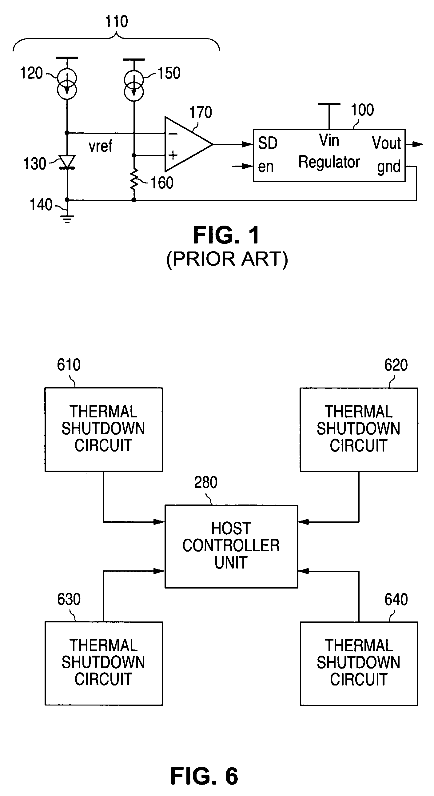
[0018]FIG. 1 illustrates a prior art voltage regulator 100 with a prior art thermal shutdown circuit 110. The basic task of the thermal shutdown circuit 110 is to immediately cut the power at the output voltage (Vout) of the voltage regulator 100 when the die temperature reaches the preselected shutdown temperature.

[0019]Prior art thermal shutdown circuit 110 comprises a first current source 120 having an output coupled to an input of diode 130. The output of diode 130 is coupled to ground 140. The prior art thermal shutdown circuit 110 also comprises a second current...


PUM


Abstract

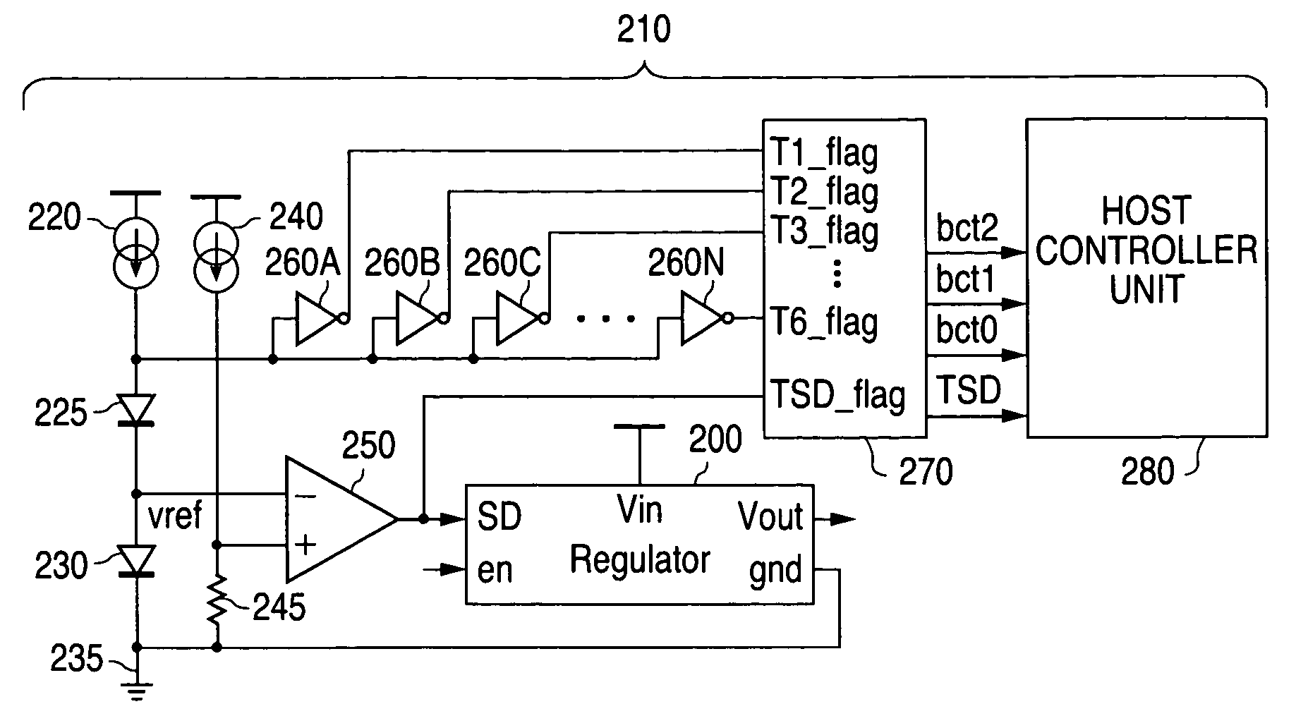
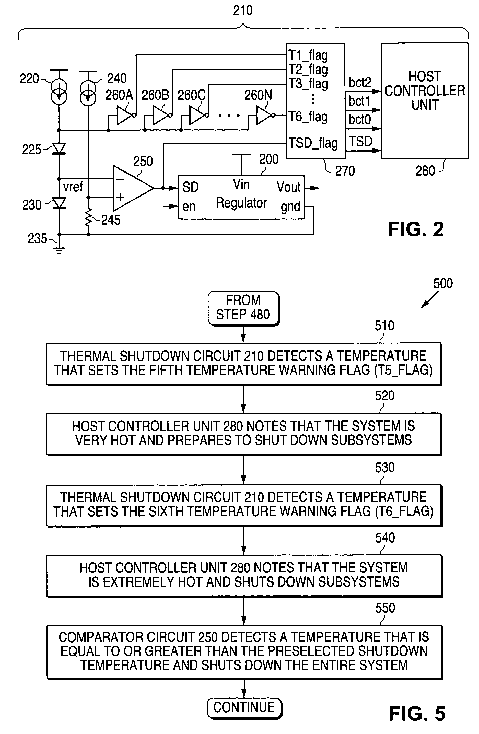
A system and method is disclosed that provides a thermal shutdown circuit that generates a plurality of temperature warning flag signals. Each temperature warning flag signal represents a different temperature. The thermal shutdown circuit comprises a plurality of inverter circuits in which each inverter circuit has a different temperature turn-on threshold. A temperature to binary code converter receives the temperature warning flag signals from the inverter circuits and generates a plurality of binary coded signals that represent a temperature that is detected by the thermal shutdown circuit. A host controller unit uses the temperature information from the binary coded signals to shut down subsystems in advance of an abrupt thermal shutdown of a system.

Description

TECHNICAL FIELD OF THE INVENTION[0001]The present invention relates generally to the manufacture of semiconductor devices and, more particularly, to a system and method for providing a thermal shutdown circuit with temperature warning flags for use in a voltage regulator circuit.BACKGROUND OF THE INVENTION[0002]A thermal shutdown (TSD) circuit is a type of circuit that is often found in linear and switching regulators and power management devices. Almost all power regulator and converter integrated circuits have an on-chip thermal shutdown circuit that monitors the temperature of the integrated circuit die.[0003]Prior art thermal shutdown circuits are usually designed to continually sense the temperature of an integrated circuit die (referred to as “the die temperature”). When the die temperature increases to a preselected threshold value of temperature (referred to as “the shutdown temperature”), the thermal shutdown circuit abruptly cuts off power to the integrated circuit. This r...

Claims


Application Information

Patent Timeline
IPC IPC(8): G05F3/26
CPCH02H5/044
Inventor WONG, KERN W.
Owner NAT SEMICON CORP
Learn More