Resettable tumbler lock

Inactive Publication Date: 2008-11-25
LIN SHENG TING
View PDF11 Cites 12 Cited by
  • Summary
  • Abstract
  • Description
  • Claims
  • Application Information

AI Technical Summary

Problems solved by technology

The conventional resettable tumbler lock is disadvantageous in that since the shapes of the holes in the first sleeve are circular and are identical to those of the blind bores in the latch-connecting part, an innermost tumbler pad in the respective hole in the first sleeve tends to be undesirably moved across the interface between the first sleeve and the latch-connecting part and to extend into an aligned hole in the latch-connecting part, which is aligned with the hole in the first sleeve, by the reset key during rotation of the first sleeve from the resettable angular position to the normal angular position, which results in a deadlock situation in which the first sleeve cannot be further rotated to the normal angular position by the reset key and the reset key cannot be removed from the keyhole.

Method used


Image

  • Resettable tumbler lock
  • Resettable tumbler lock
  • Resettable tumbler lock

Examples


Embodiment Construction

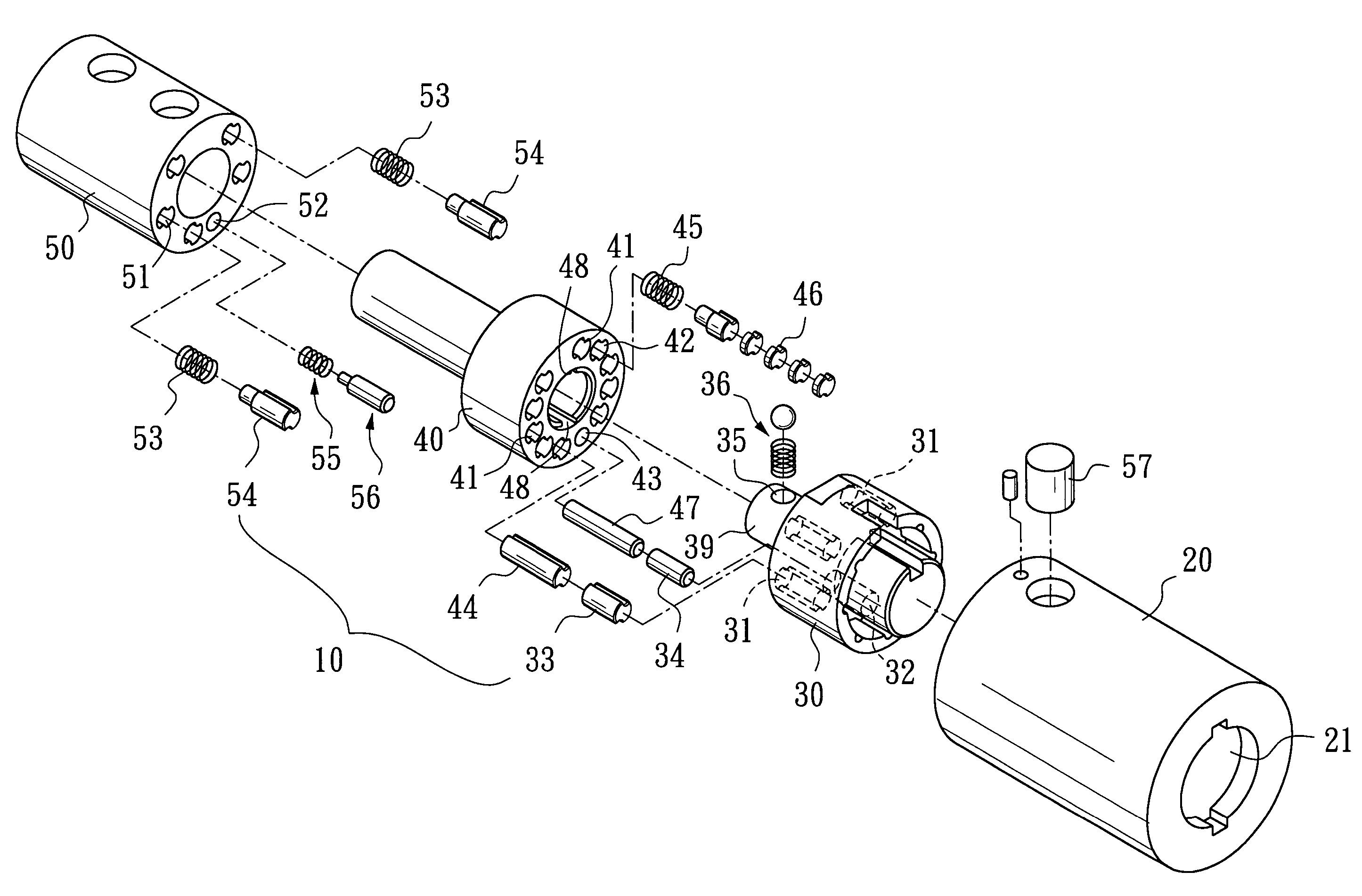
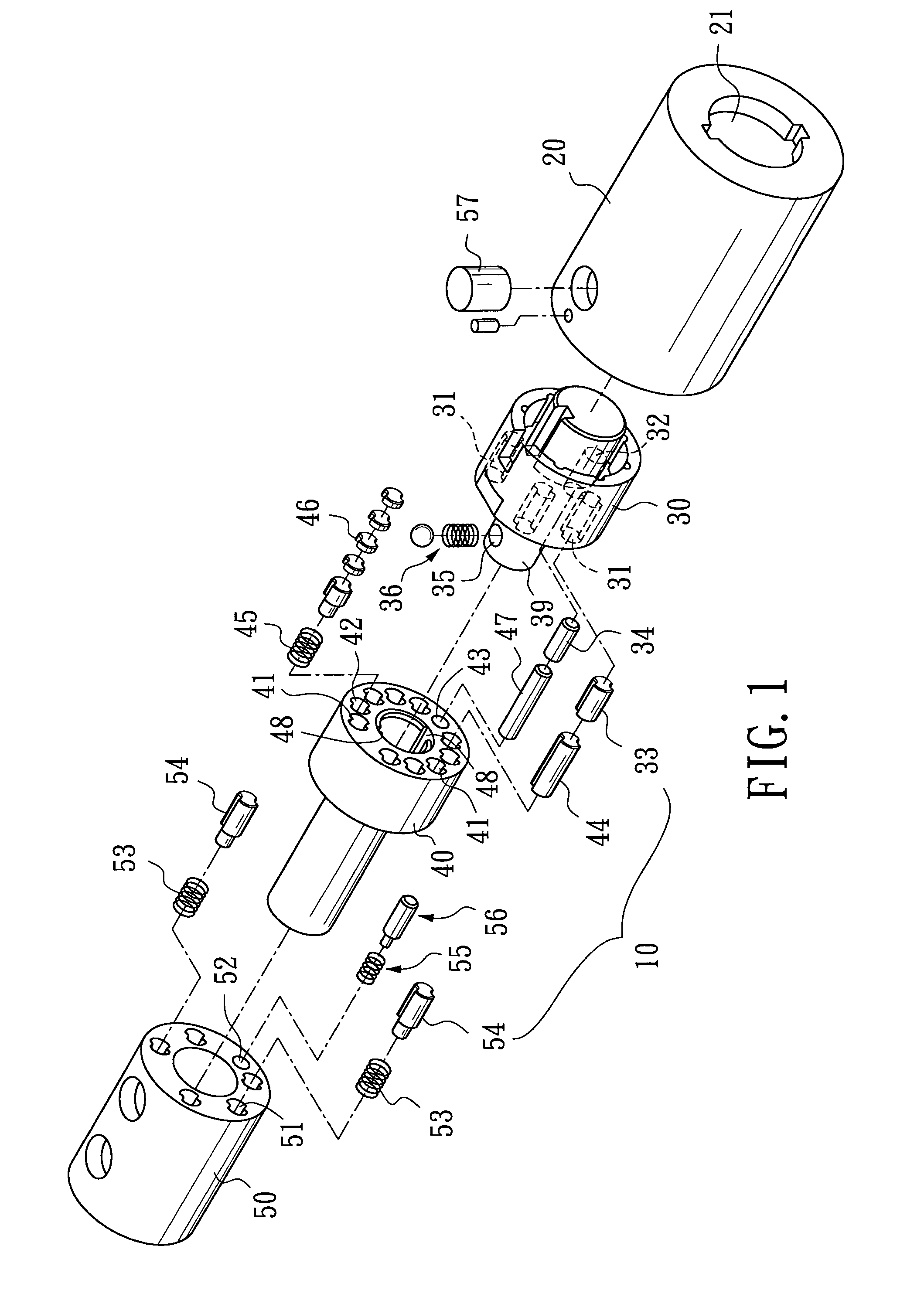
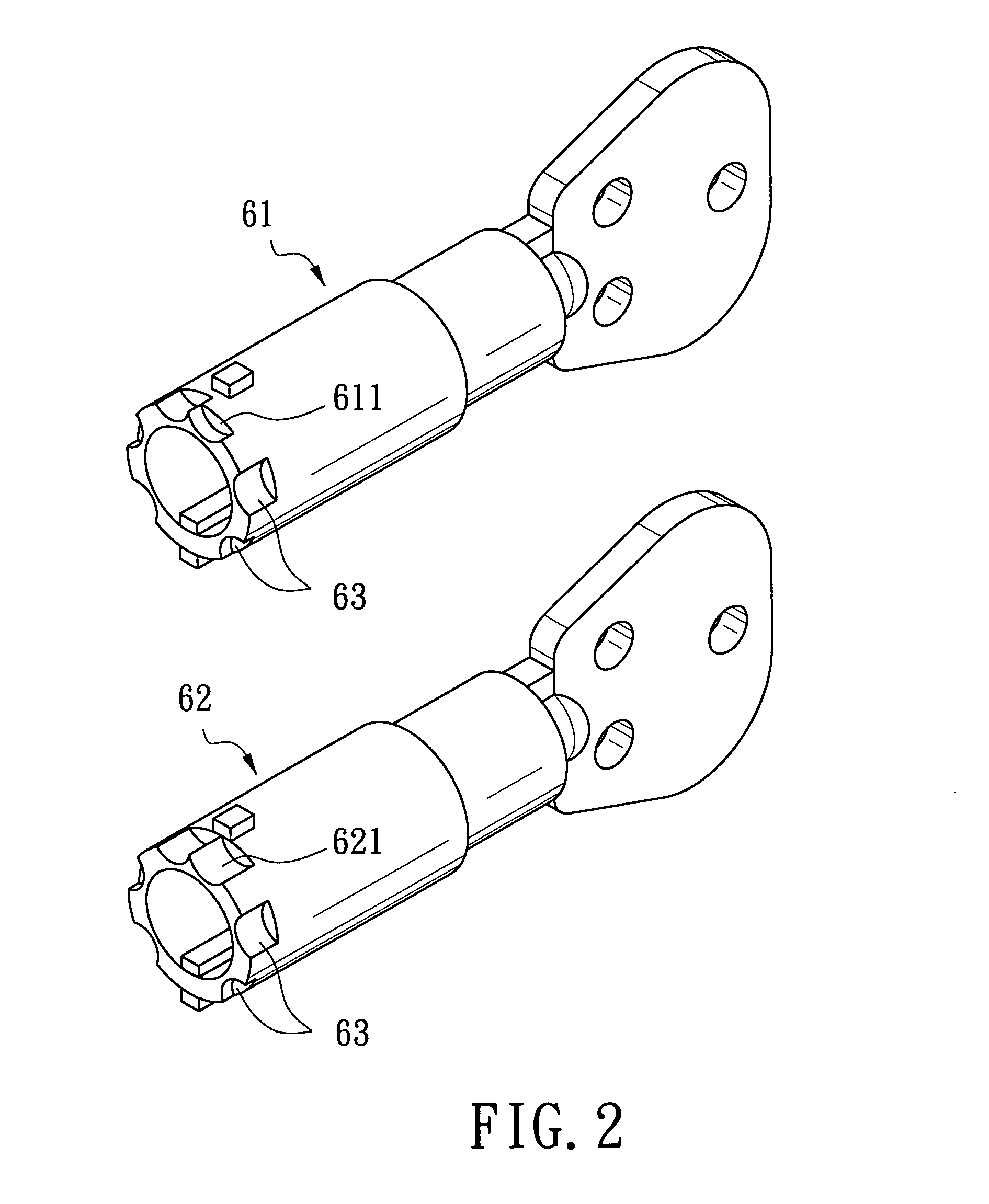
[0026]FIGS. 1 and 5 illustrate the preferred embodiment of a resettable tumbler lock according to this invention. The resettable tumbler lock includes: a cylindrical lock housing 20 defining a keyhole 21; a first sleeve 30 mounted coaxially and rotatably in the lock housing 20 and formed with a plurality of tumbler bores 31 (see FIG. 3); a cylindrical latch-connecting part 40 mounted coaxially and rotatably in the lock housing 20 and in end-to-end contact with the first sleeve 30, the latch-connecting part 40 being formed with a plurality of circumferentially disposed tumbler holes 41 and a plurality of circumferentially disposed blind holes 42 (see FIG. 4) that are angularly displaced with the tumbler holes 41; and a plurality of spring-biased tumbler units 10, each of which is disposed movably in a respective one of the tumbler bores 31, a respective one of the tumbler holes 41, and a respective one of the blind holes 42. The first sleeve 30 is operable using a reset key 61 (see F...


PUM


Abstract

A resettable tumbler lock includes: a lock housing; a sleeve mounted rotatably in the lock housing and formed with a plurality of tumbler bores; a cylindrical latch-connecting part mounted rotatably in the lock housing and formed with a plurality of tumbler holes and a plurality of blind holes; and a plurality of spring-biased tumbler units. The sleeve is rotatable relative to the latch-connecting part between first and second angular positions. At least one of the tumbler bores in the sleeve has an axial projection that does not coincide with that of an aligned one of the tumbler holes in the latch-connecting part when the sleeve is disposed at a predetermined position between the first and second angular positions.

Description

BACKGROUND OF THE INVENTION[0001]1. Field of the Invention[0002]This invention relates to a resettable tumbler lock, more particularly to a resettable tumbler lock having tumbler holes with cross sections that differ from each other in at least one of the group consisting of shape, size, and orientation.[0003]2. Description of the Related Art[0004]U.S. Pat. No. 6,550,299 discloses a conventional resettable tumbler lock that includes a housing, a first sleeve mounted rotatably in the housing and formed with a plurality of axially extending holes and a first locking hole, a second sleeve mounted in and secured to the housing and formed with a plurality of axially extending holes and a second locking hole, a cylindrical latch-connecting part disposed between and in end-to-end contact with the first and second sleeves and formed with a plurality of axially extending holes and a middle locking hole, and a plurality of spring-biased tumbler units including first tumbler pins disposed mova...

Claims


Application Information

Patent Timeline
Patent Type & Authority Patents(United States)
IPC IPC(8): E05B27/00E05B29/00
CPCE05B27/005E05B27/083Y10S70/37Y10T70/7701Y10T70/7593Y10T70/7853Y10T70/7525
Inventor LIN, SHENG-TING
Owner LIN SHENG TING
Why Eureka
Try Eureka