
Cold-forging technique of gear shaft

A gear shaft, cold forging technology, applied in metal material coating process, manufacturing tools, metal processing equipment and other directions, can solve the problems of low back extrusion deformation of tooth blind holes, insufficient tooth strength, low production efficiency, etc. Achieve the effect of improving the quality and production efficiency of gear hole forming, saving raw materials and improving production efficiency

Inactive Publication Date: 2008-12-31
SHANGHAI DONGFU COLD FORGING MFG
View PDF0 Cites 55 Cited by
  • Summary
  • Abstract
  • Description
  • Claims
  • Application Information

AI Technical Summary

Problems solved by technology

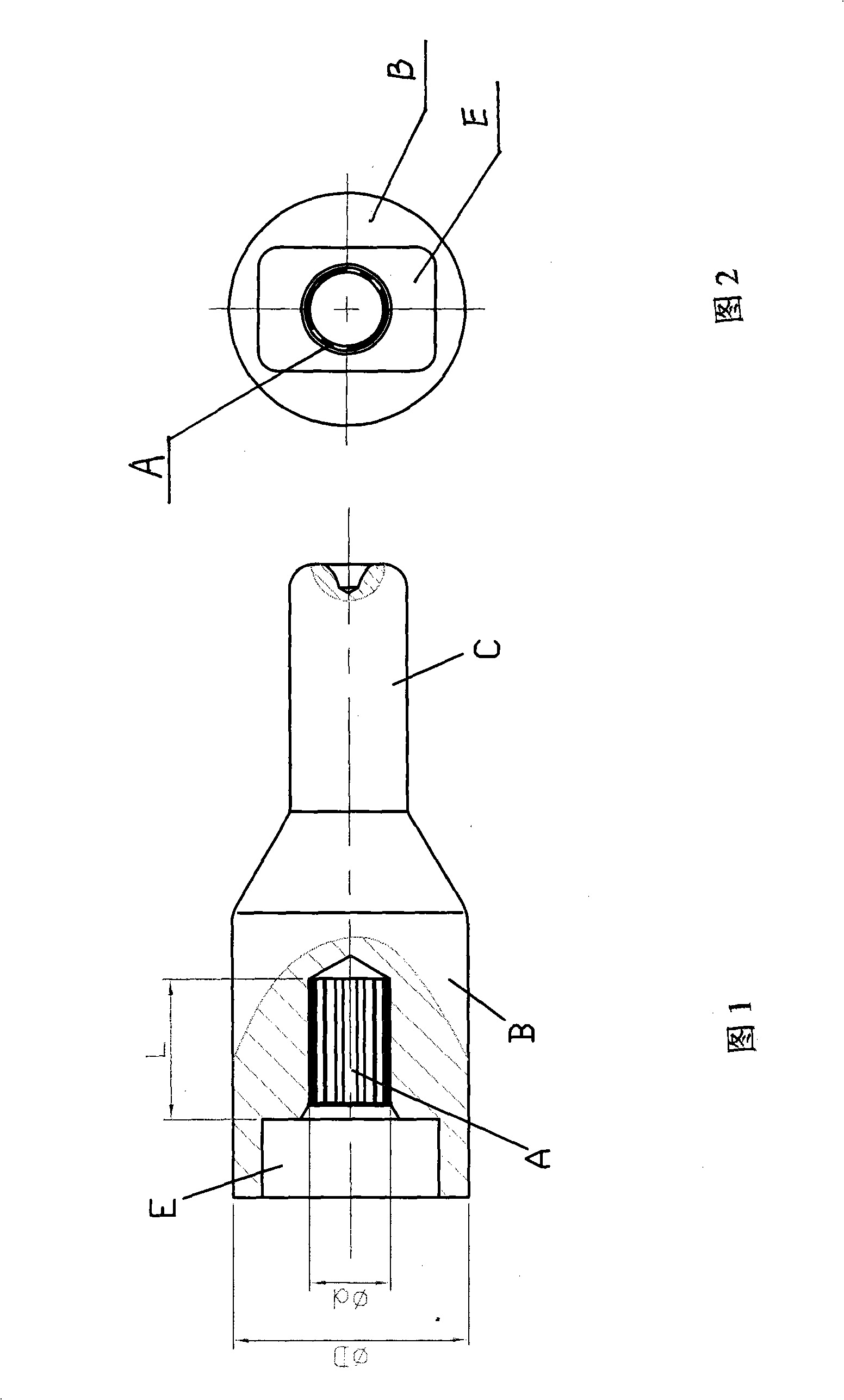
[0002] At present, the gear shaft is to be processed, as shown in Figures 1 and 2, the shape of the gear shaft is composed of a large end B and a small end C, and the large end B has a rectangular inner hole E and a toothed blind hole A. The traditional processing method The outer shape and the inner square hole are formed by cutting or forging, while the tooth-shaped blind hole has an extremely low amount of deformation due to back extrusion (ε F = d 2 / D 2 =0.10~0.12), greatly exceeding the allowable limit deformation of cold forging (ε F ≥0.2), the mold withstands unit extrusion force up to 400Kg / mm 2 , also much more than 250 ~ 300Kg / mm 2 Generally, forging cannot be carried out, so it can only be drilled first and then cut. The disadvantages of drilling and cutting are insufficient tooth profile strength, poor consistency, low production efficiency and waste of materials.

Method used


Image

  • Cold-forging technique of gear shaft
  • Cold-forging technique of gear shaft
  • Cold-forging technique of gear shaft

Examples


Embodiment

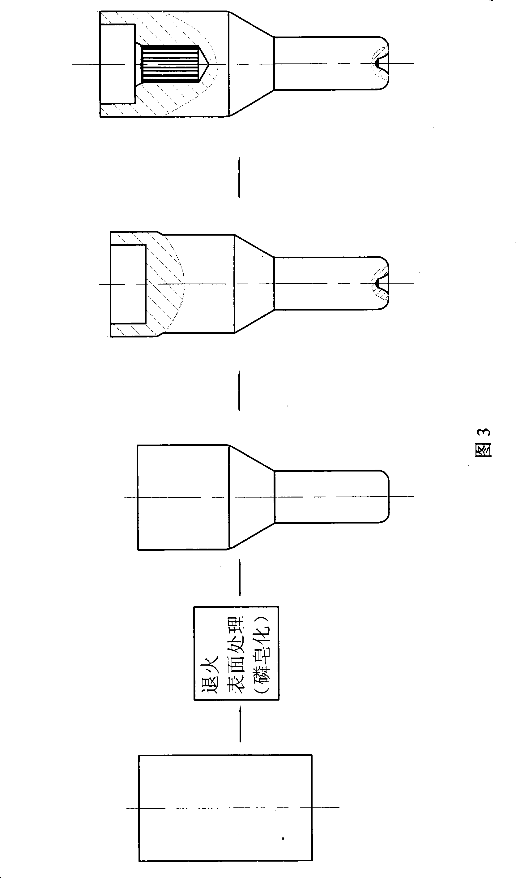
[0023] As shown in Figure 3, it is a cold forging process flow chart, and a cold forging process for a gear shaft is:

[0024] In the first step, according to the length of the gear shaft, the alloy steel bar is blanked with a circular saw machine, and the weight error of the blank is ±1 gram;

[0025] The second step is to anneal the rough bar in a well-type furnace at an annealing temperature of 860°C, hold it for 6 hours, and cool it to 300°C with the furnace;

[0026] The third step is to use the phosphorus saponification line to carry out phosphating and saponification treatment on the annealed blank bar according to the conventional process to form a surface lubricating layer. The phosphating temperature is 70 ° C and the time is 20 minutes; the saponification temperature is 60 ° C and the time for 10 minutes;

[0027] The fourth step is to use high-strength die steel to manufacture forward extrusion dies, reverse extrusion dies and gear hole forming dies;

[0028] The...


PUM


Abstract

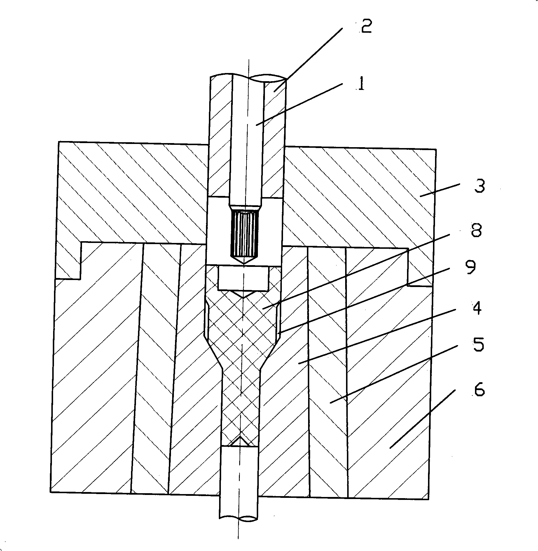
The invention relates to a cold forging technology for a gear shaft; the cold forging technology is characterized in that a new technology of the cold forging forming of the inside and outside and split flow forging, a volume split flow space is arranged between the gear shaft diameter and a concave die, the metal flow resistance is reduced and the unit extruding force carried by the die is lowered by split flow; high-strength die steel and split structure are adopted to produce a gear hole forming die; the concave die is produced by adopting three-layer sleeve prestressed structure so as to improve the compression resistance of the die; a punch is made from an alloy steel material and used for the cold forging and precision forming of a complex gear form blind hole, which improves the forming quality and production efficiency of the gear hole, and lowers the consumption of the raw materials markedly. The cold forging technology of the invention has the advantages of achieving the smooth forming of the gear form blind hole, improving the production efficiency greatly, and improving the quality of the gear hole and the qualification rate of the product markedly.

Description

technical field [0001] The invention relates to a cold forging process of a gear shaft, in particular to a precision cold forging process for a steering system gear shaft of a car, and belongs to the technical field of cold forging precision forming process. Background technique [0002] At present, the gear shaft is to be processed, as shown in Figures 1 and 2, the shape of the gear shaft is composed of a large end B and a small end C, and the large end B has a rectangular inner hole E and a toothed blind hole A. The traditional processing method The outer shape and the inner square hole are formed by cutting or forging, while the tooth-shaped blind hole has an extremely low amount of deformation due to back extrusion (ε F = d 2 / D 2 =0.10~0.12), greatly exceeding the allowable limit deformation of cold forging (ε F ≥0.2), the mold withstands unit extrusion force up to 400Kg / mm 2 , also much more than 250 ~ 300Kg / mm 2 Generally, forging cannot be carried out, so it can...

Claims


Application Information

Patent Timeline
IPC IPC(8): B21K1/06B21J13/02C21D1/26C23C22/07
Inventor 廖世绍廖泽寰
Owner SHANGHAI DONGFU COLD FORGING MFG
Learn More