Electrostatic spray assembly

a technology of electrostatic assembly and spray nozzle, which is applied in the direction of induction-charged spraying, mechanical equipment, lighting and heating equipment, etc., can solve the problems of affecting the spray distribution, significantly affecting the spray operation efficiency, and affecting the spray operation. achieve the effect of more efficient and reliable spraying

Active Publication Date: 2008-11-25
SPRAYING SYST
View PDF8 Cites 4 Cited by
  • Summary
  • Abstract
  • Description
  • Claims
  • Application Information

AI Technical Summary

Benefits of technology

[0005]It is an object of the present invention to provide an electrostatic spray nozzle assembly that is adapted for more efficient and reliable spraying of oils and other lubricating and coating fluids.
[0006]Another object is to provide an electrostatic spray nozzle assembly which includes electrostatic charging electrodes that are adapted for more precise manufacture and mounting within the nozzle assembly, and hence more efficient operation with reduced power consumption and increased life expectancy.
[0008]Still another object is to provide an electrostatic spray nozzle assembly of the above kind which is adapted for more effectively atomizing the fluid flow streams so as to produce a uniform fine particle distribution onto items being sprayed.
[0009]Still another object is to provide an electrostatic spray nozzle assembly that can have relatively large fluid passages that resist clogging and are easy to clean.
[0010]Still another object is to provide an electrostatic spray nozzle assembly that requires a relatively low voltage at the nozzle tip thereby improving safety and reducing the tendency of sparking.
[0011]Yet another object is to provide such an electrostatic spray nozzle assembly which is relative simple in construction and lends itself to economical manufacture.

Problems solved by technology

Heretofore, such electrostatic assembly spray nozzle assemblies have suffered from various operating and maintenance problems.
For example, imprecise manufacture and assembly of such spray nozzles and charging electrodes can result in high voltage leakage that can significantly affect the operating efficiency of the spray operation.
Fluid leakage problems also can adversely affect the spray distribution and lead to waste of costly spray liquids.

Method used


Image

  • Electrostatic spray assembly
  • Electrostatic spray assembly
  • Electrostatic spray assembly

Examples


Embodiment Construction

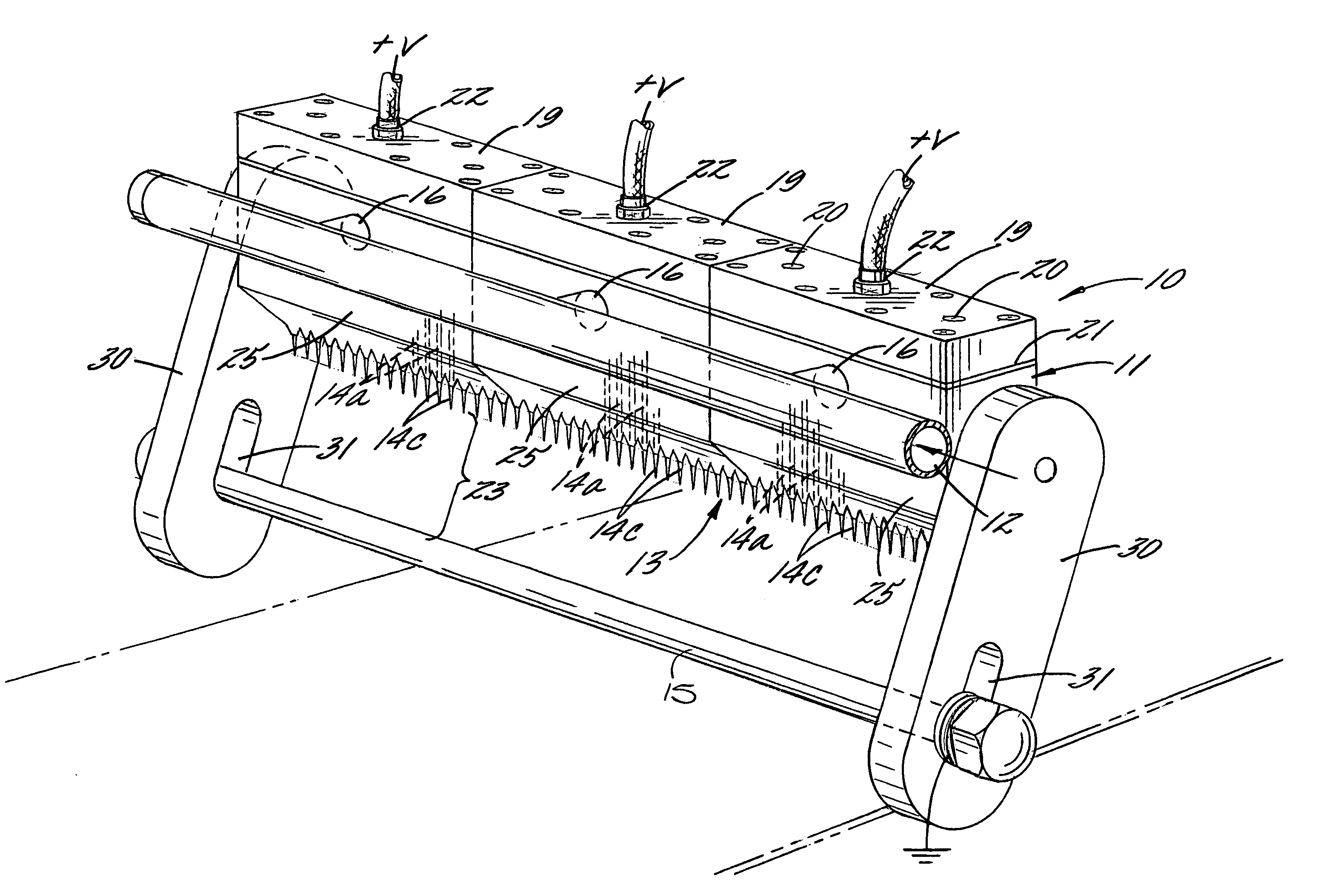
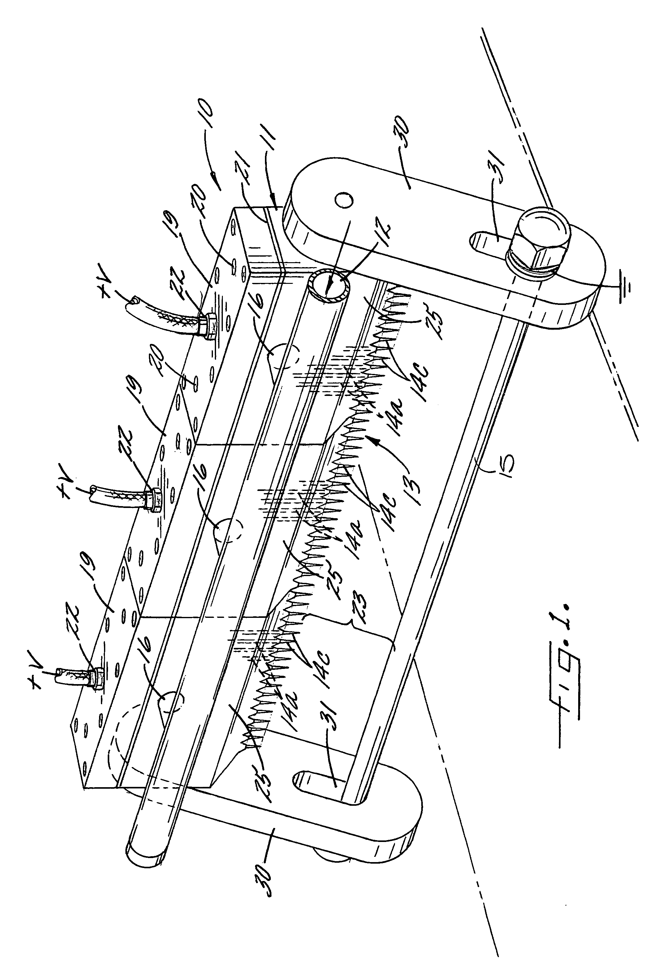
[0026]Referring now more particularly to the drawings, there is shown in FIGS. 1 and 2 an illustrative electrostatic spraying assembly 10 embodying the present invention, which is adapted for directing an elongated spray of oil or other lubricating or coating fluid on items conveyed below the spray assembly 10. The illustrative spray nozzle assembly 10 basically comprises an elongated housing 11 supported in adjacent relation to a fluid supply pipe 12, an electrode assembly 14 for charging fluid passing through and directed from a lower discharge end 13 of the housing 11, and an induction bar 15 disposed in parallel spaced relation to the discharge end of the housing 11 for enhancing liquid particle breakdown. The housing 11 in this case is supported by the fluid supply pipe 12 by means of a plurality of transversely directed conduit sections 16 that communicate between the fluid supply pipe 12 and fluid inlet ports 16a in a side of the housing.

[0027]In accordance with an important ...


PUM


Abstract

An electrostatic spraying assembly is provided. The spraying assembly includes a housing having a fluid inlet passage that is connectable to a fluid source and communicates with a plurality of discharge passageways each of which extends through the housing to a downstream end at a discharge end of the housing. The housing has a one piece construction and is made of an electrically insulative material. The spraying assembly also includes an electrode assembly. The electrode assembly includes a plurality of elongate electrode elements each of which is disposed in a respective one of the discharge passageways in the housing and an electrode header. The electrode header is electrically connectable to a voltage source and each of the electrode elements is electrically connectable to the electrode header.

Description

CROSS-REFERENCE TO RELATED PATENT APPLICATIONS[0001]This patent application claims the benefit of U.S. Provisional Patent Application No. 60 / 544,269 filed on Feb. 12, 2004.FIELD OF THE INVENTION[0002]The present invention relates generally to spray nozzle assemblies, and more particularly, to electrostatic spray nozzle assemblies that electrostatically charge fluids discharging from spray nozzles to facilitate liquid particle breakdown and distribution.BACKGROUND OF THE INVENTION[0003]Electrostatic spray nozzle assemblies are utilized for applying oil and other coating and lubricating fluids in various manufacturing processes. Electrostatic spray nozzle assemblies, such as shown in U.S. Pat. No. 4,749,125, discharge a plurality of fluid flow streams which are electrostatically charged and atomized by means of a high voltage electrode with the assistance of a grounded induction bar for disposition onto items to be sprayed or coated, typically as they are conveyed past the spraying ap...

Claims


Application Information

Patent Timeline
Patent Type & Authority Patents(United States)
IPC IPC(8): B05B5/00B05B5/025B05B5/053
CPCB05B1/202B05B5/035B05B5/043B05B5/0533B05B1/20F16N7/34
Inventor MULJONO, ERIC BUDI
Owner SPRAYING SYST
Why Eureka
Try Eureka