Electrostatic spray assembly

a technology of electrostatic assembly and spray nozzle, which is applied in the direction of dental surgery, lighting and heating apparatus, combustion types, etc., can solve the problems of affecting the spray distribution, significantly affecting the operating efficiency of the spray operation, and affecting the spray operation. achieve the effect of more efficient and reliable spraying

Active Publication Date: 2012-10-16
SPRAYING SYST
View PDF7 Cites 2 Cited by
  • Summary
  • Abstract
  • Description
  • Claims
  • Application Information

AI Technical Summary

Benefits of technology

[0005]It is an object of the present invention to provide an electrostatic spray nozzle assembly that is adapted for more efficient and reliable spraying of oils and other lubricating and coating fluids.
[0006]Another object is to provide an electrostatic spray nozzle assembly which includes electrostatic charging electrodes that are adapted for more precise manufacture and mounting within the nozzle assembly, and hence more efficient operation with reduced power consumption and increased life expectancy.
[0008]Still another object is to provide an electrostatic spray nozzle assembly of the above kind that can be efficiently controlled for repeated cyclic operation without undesirable drippage during shut-off.
[0009]Another object is to provide an electrostatic spray nozzle assembly that has relatively large fluid passages that resist clogging and are easy to clean.
[0010]Yet a further object is to provide such an electrostatic spray nozzle assembly which is relative simple in construction and lends itself to economical manufacture.

Problems solved by technology

Heretofore, such electrostatic assembly spray nozzle assemblies have suffered from various operating and maintenance problems.
For example, imprecise manufacture and assembly of such spray nozzles and charging electrodes can result in high voltage leakage that can significantly affect the operating efficiency of the spray operation.
Fluid leakage problems also can adversely affect the spray distribution and lead to waste of costly spray liquids.
While it often is desirable to direct a plurality of electro-statically charged flow streams, heretofore it has been difficult to effectively and efficiently control the liquid discharge for cyclic operation and without undesirable dripping and waste of the coating fluid.

Method used


Image

  • Electrostatic spray assembly
  • Electrostatic spray assembly
  • Electrostatic spray assembly

Examples


Embodiment Construction

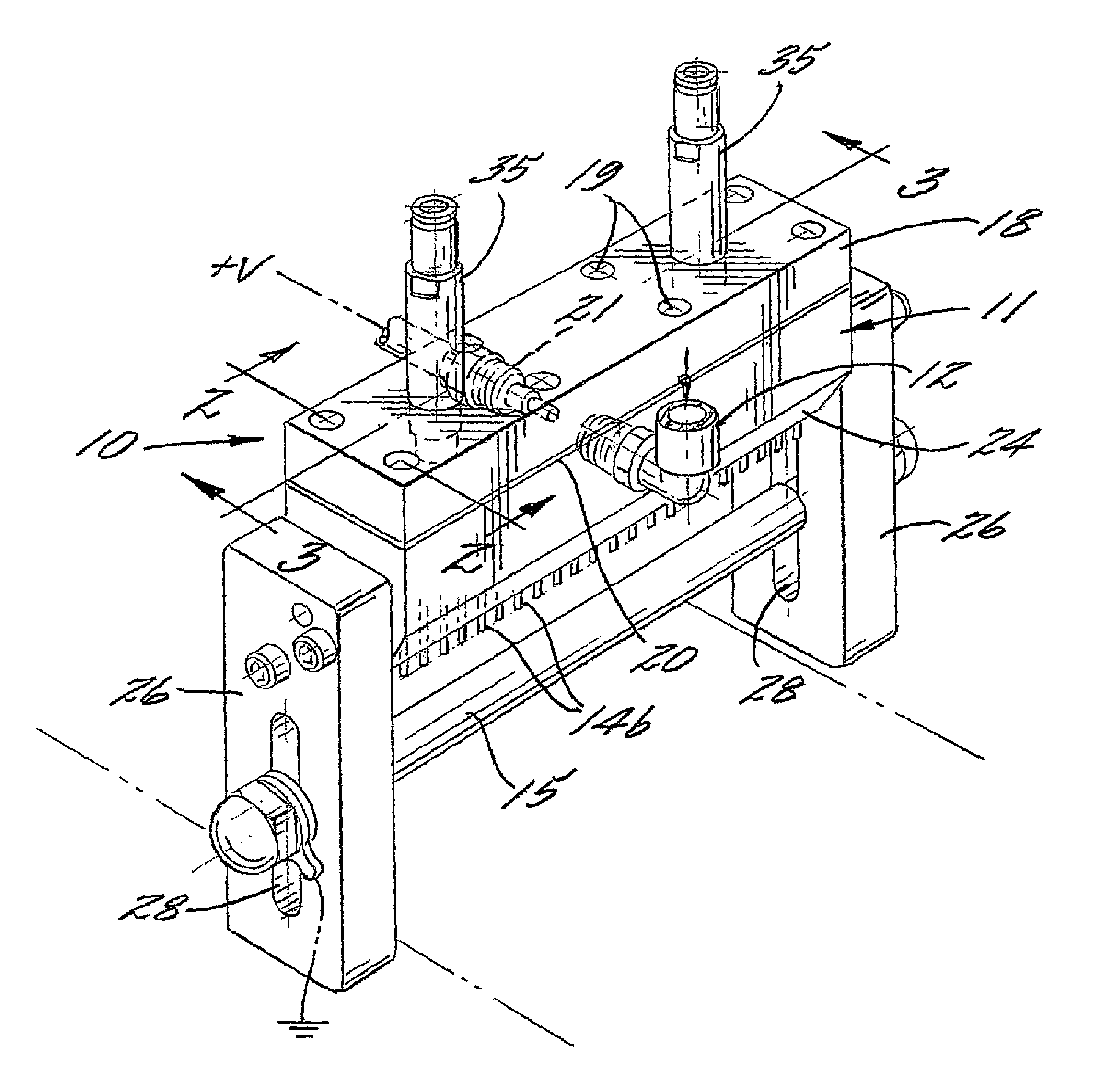
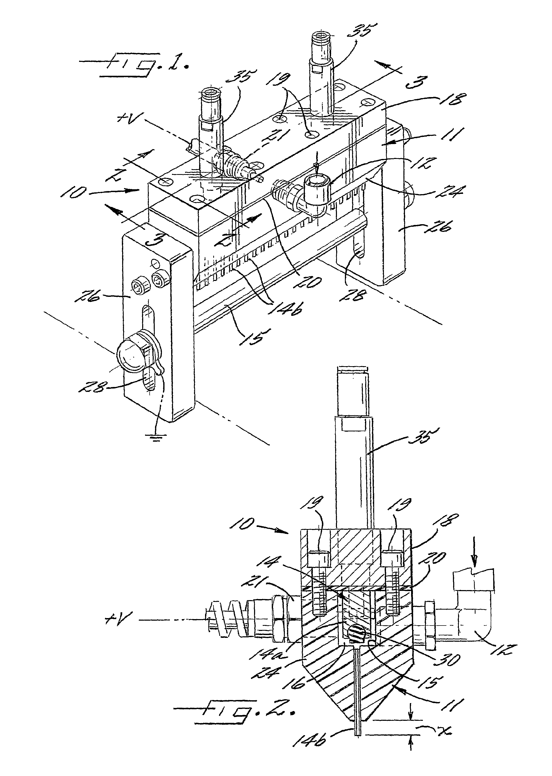
[0017]Referring now more particularly to the drawings, there is shown in an illustrative electrostatic spray nozzle assembly 10 embodying the present invention, which is adapted for directing an elongated spray of oil or other lubricating or coating fluid on items conveyed below the spray assembly 10. The illustrative spray assembly 10 basically comprises a non-metallic elongated housing 11 having an inlet port connected to a fluid supply pipe 12 that supplies liquid coating or other fluid materials to the spray assembly 10, an electrode assembly 14 within the spray housing 11 for charging fluid passing through and directed from a lower discharge end of the housing 11, and an induction bar 15 disposed in parallel spaced relation to the discharge end of the housing 11 for generating an electrical field to enhance liquid particle breakdown. It will be appreciated that the housing 11 may be appropriately supported by support brackets or the like in overlying relation to items to be spr...


PUM


Abstract

An electrostatic spraying assembly including a housing and a plurality of elongated electrode elements supported within the housing each defining a respective fluid passageway. An electrode header connectable to a high voltage source is supported within the housing in spaced relation to the electrode elements for charging the electrodes to an electrical potential by induction, and in turn, charging liquid directed through the passageways. The electrode header and a resilient valve element supported thereon are movable between retracted and closing positions for controlling the flow of fluid through the electrode passageways for discharge into an electrical field generated by an induction element supported in spaced relation to the discharge ends of the electrode elements.

Description

CROSS-REFERENCE TO RELATED PATENT APPLICATIONS[0001]The present application claims the benefit of U.S. Provisional Patent Application No. 60 / 733,289 filed Nov. 3, 2005, and is a continuation-in-part of application Ser. No. 11 / 056,703 filed Feb. 11, 2005, which in turn claims the benefit of U.S. Provisional Patent Application No. 60 / 544,269 filed on Feb. 12, 2004, the disclosures of which are incorporated herein by reference.FIELD OF THE INVENTION[0002]The present invention relates generally to spray nozzle assemblies, and more particularly, to electrostatic spray nozzle assemblies that electrostatically charge fluids discharging from spray nozzles to facilitate liquid particle breakdown and distribution.BACKGROUND OF THE INVENTION[0003]Electrostatic spray nozzle assemblies are utilized for applying oil and other coating and lubricating fluids in various manufacturing processes. Electrostatic spray nozzle assemblies, such as shown in U.S. Pat. No. 4,749,125, discharge a plurality of ...

Claims


Application Information

Patent Timeline
Patent Type & Authority Patents(United States)
IPC IPC(8): B05B5/00
CPCB05B1/202B05B1/306B05B5/035B05B5/043B05B5/0533F16N7/34Y10T137/86879Y10T137/87708
Inventor MULJONO, ERIC BUDI
Owner SPRAYING SYST
Why Eureka
Try Eureka