Support arm mechanism

a technology of supporting arm and mechanism, which is applied in the direction of movable shelf cabinets, machine supports, building scaffolds, etc., can solve the problems of limited storage size, keyboards and monitors that cannot be moved, and desks designed for writing become inadequate, so as to achieve the effect of reducing the space required for storage of the supporting arm mechanism

Active Publication Date: 2008-11-25
WEBER KNAPP
View PDF21 Cites 15 Cited by
  • Summary
  • Abstract
  • Description
  • Claims
  • Application Information

AI Technical Summary

Benefits of technology

[0010]Another object of the invention is to minimize the space required to store the support arm mechanism.
[0011]Yet another object of the invention is to provide positive feedback regarding ergonomic factors of the support arm mechanism configuration, e.g., support height and angle.

Problems solved by technology

For example, with the introduction of the typewriter, desks designed for writing became inadequate.
Similarly, as personal computers began overtaking the work environment, keyboards and monitors presented new issues to accommodate.
Although the device taught in this patent elegantly provides the aforementioned movement and locking capabilities, the storage size is limited by the size of the mechanism and the length of the guide track upon which the mechanism travels.
Further issues presented to office designers include ergonomic considerations, specifically when faced with the situation where more than one person uses a workstation, i.e., flex and part-time employees.
However, heretofore, no support arm mechanisms have provided height and angle information, as described above.
Heretofore, tradeoffs between functionality and storage size were required.
Additionally, ergonomic factors have driven support arm mechanism design, but positive feedback of support height and angle has not been considered.

Method used


Image

  • Support arm mechanism
  • Support arm mechanism
  • Support arm mechanism

Examples


Embodiment Construction

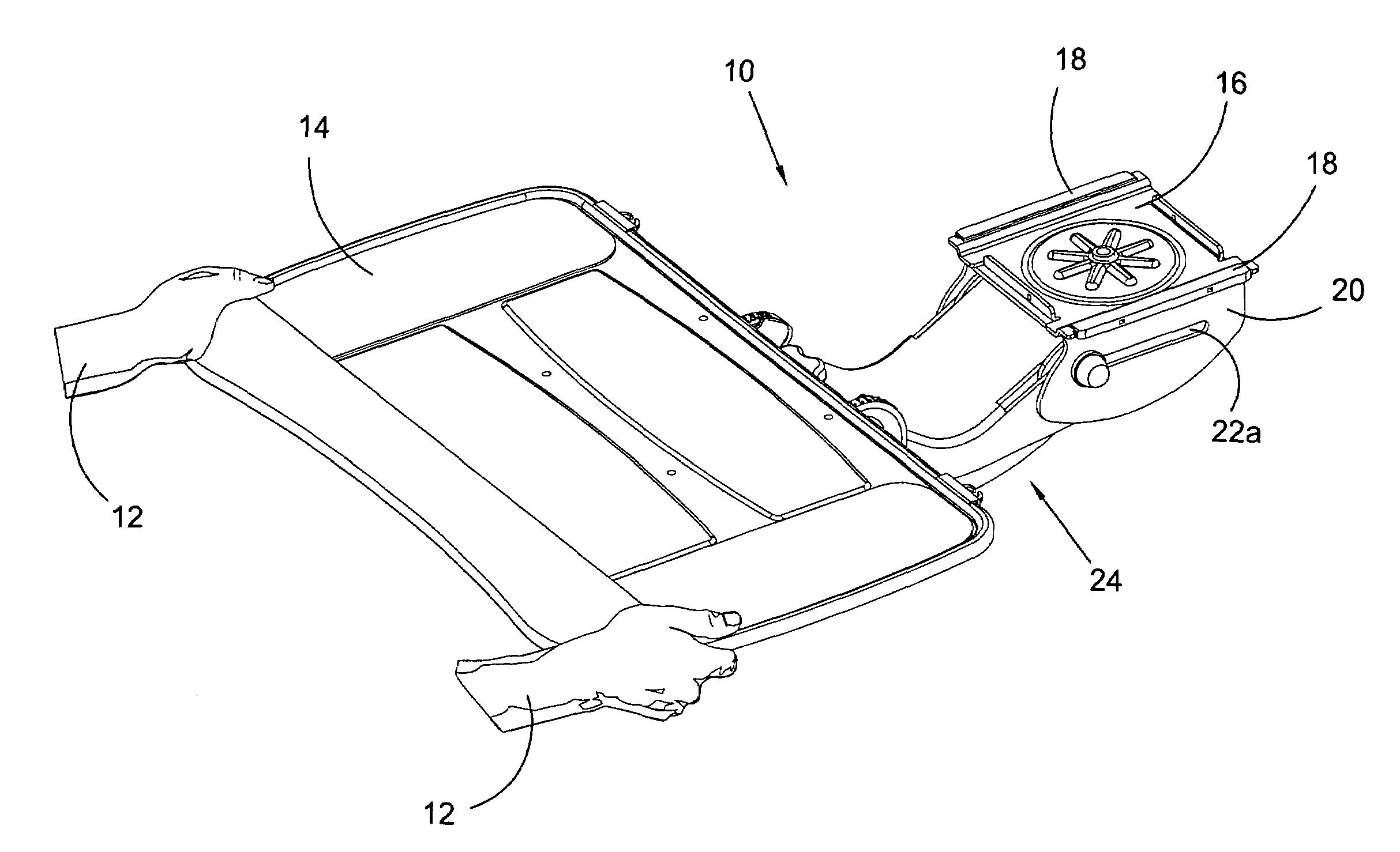
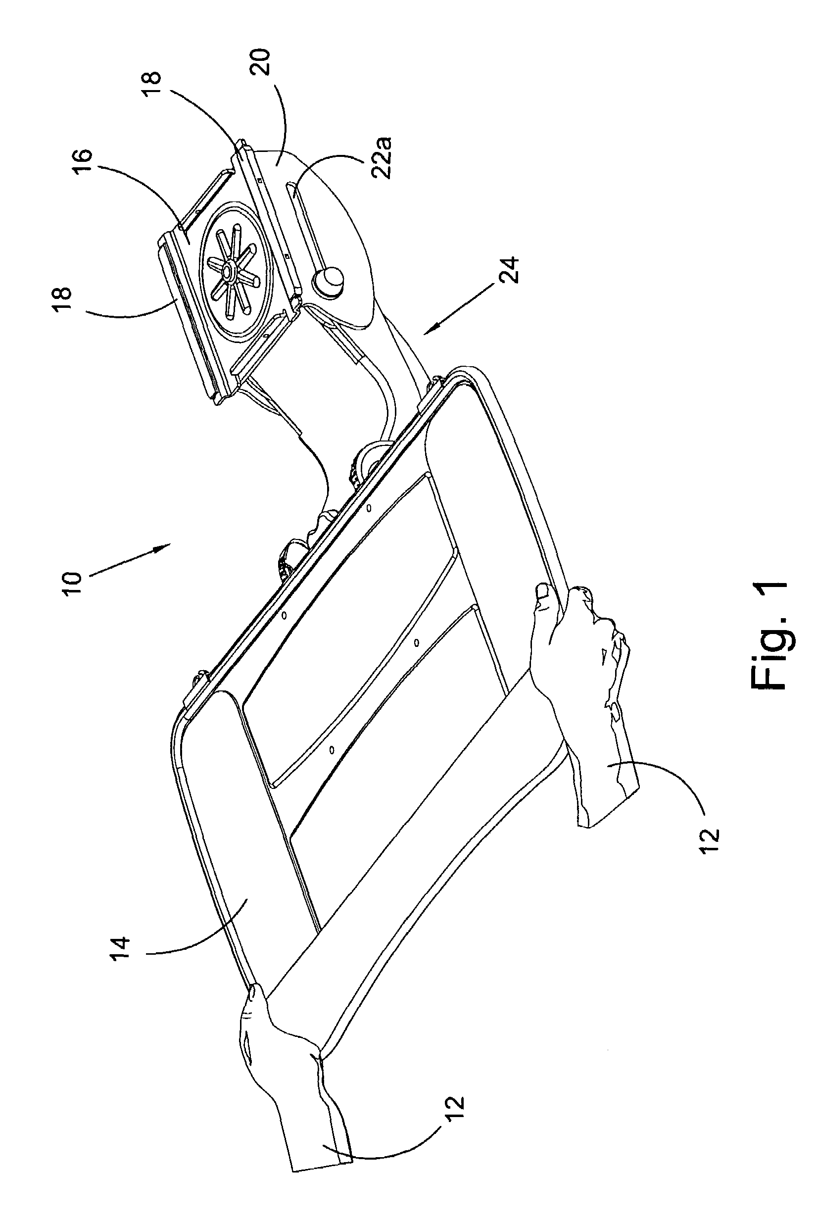
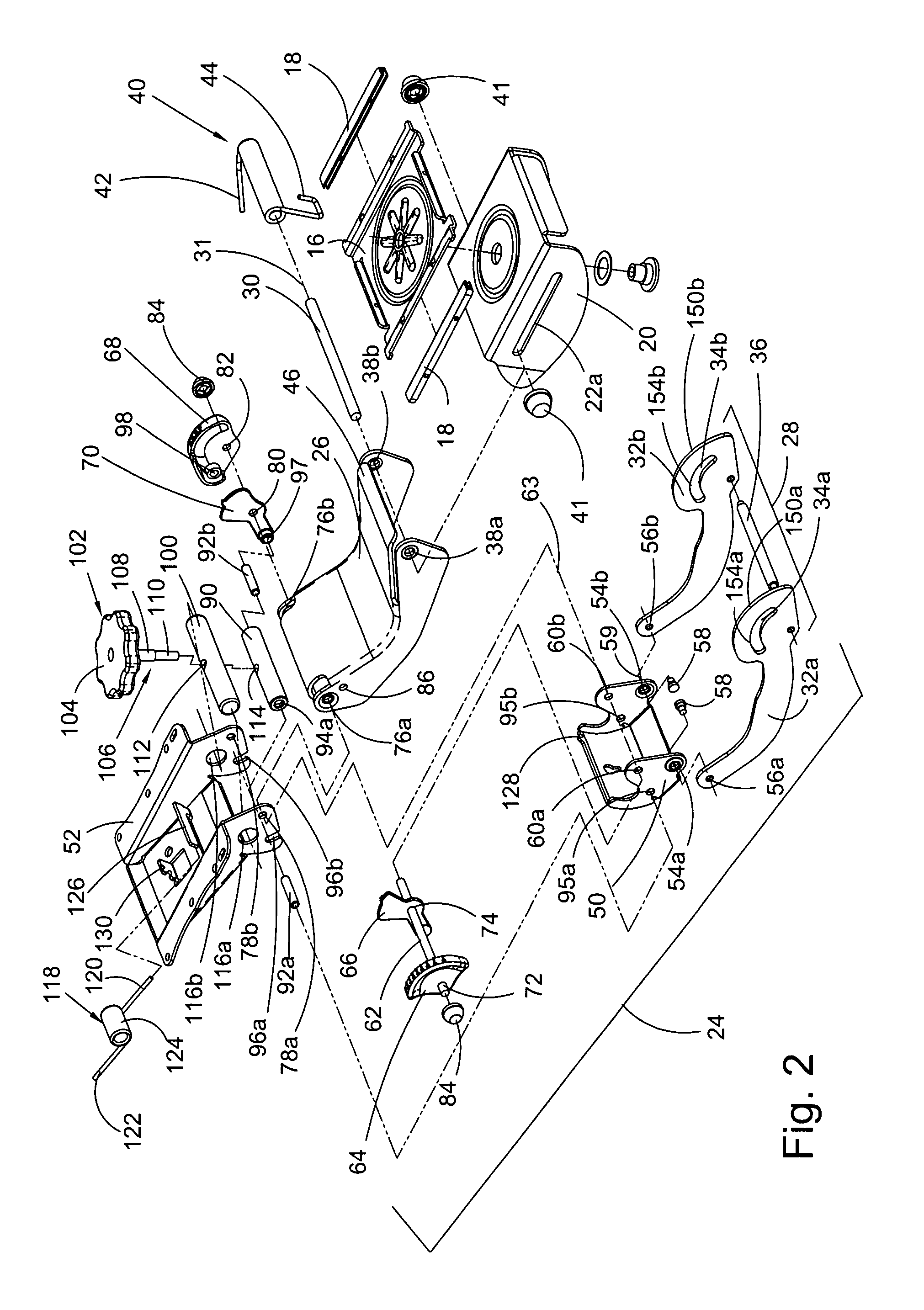
[0039]At the outset, it should be appreciated that like drawing numbers on different drawing views identify identical, or functionally similar, structural elements of the invention. While the present invention is described with respect to what is presently considered to be the preferred embodiment, it is to be understood that the invention as claimed is not limited to the preferred embodiment.

[0040]Furthermore, it is understood that this invention is not limited to the particular methodology, materials and modifications described and as such may, of course, vary. It is also understood that the terminology used herein is for the purpose of describing particular embodiments only, and is not intended to limit the scope of the present invention.

[0041]Unless defined otherwise, all technical and scientific terms used herein have the same meaning as commonly understood to one of ordinary skill in the art to which this invention belongs. Although any methods, devices or materials similar or...


PUM


Abstract

A mechanism for mounting a support including a linkage, wherein the linkage has at least three bars, the mechanism is attached to a base by a mounting member, and the mounting member has a pair of slots wherein the linkage may slide and pivot relative to the mounting member. In another embodiment, the mechanism includes a height indicator whereby a height of the mechanism relative to a height indicating surface is displayed. In a further embodiment, the mechanism includes an angle indicator whereby an angle of the support relative to an angle indicating surface is displayed. In yet another embodiment, the mechanism permits adjustment of the angle of the support relative to the angle indicating surface.

Description

FIELD OF THE INVENTION[0001]The present invention relates generally to support arms, more particularly, to a support arm for an article, and, more specifically, to a durable, high strength support arm for an article having a reduced storage size and ergonomic factor indicators.BACKGROUND[0002]Over time, desk and office furniture designs have changed with the advent and acceptance of new technologies. For example, with the introduction of the typewriter, desks designed for writing became inadequate. Typewriters did not require that the work surface be as large, nor the height of the work surface be as high. Similarly, as personal computers began overtaking the work environment, keyboards and monitors presented new issues to accommodate. As in the past, design advancements continue, resulting most recently in flat screen monitors and wireless devices, e.g., keyboard and mouse.[0003]Cost conscious businesses are always seeking ways to minimize expenses, for example, high efficiency lig...

Claims


Application Information

Patent Timeline
Patent Type & Authority Patents(United States)
IPC IPC(8): E04G3/00
CPCA47B21/0314Y10S248/918
Inventor MALONEY, ERIC W.PANGBORN, DONALD R.
Owner WEBER KNAPP
Why Eureka
Try Eureka