
Method and apparatus for dropping a launch vehicle from beneath an airplane

a technology for launching vehicles and aircraft, applied in the direction of launching weapons, cosmonautic vehicles, transportation and packaging, etc., can solve the problems of reducing the rotation rate, and achieve the effect of increasing the safety of the carrier aircra

Active Publication Date: 2008-12-02
SARIGUL KLIJN MARTI +1
View PDF13 Cites 28 Cited by
  • Summary
  • Abstract
  • Description
  • Claims
  • Application Information

AI Technical Summary

Benefits of technology

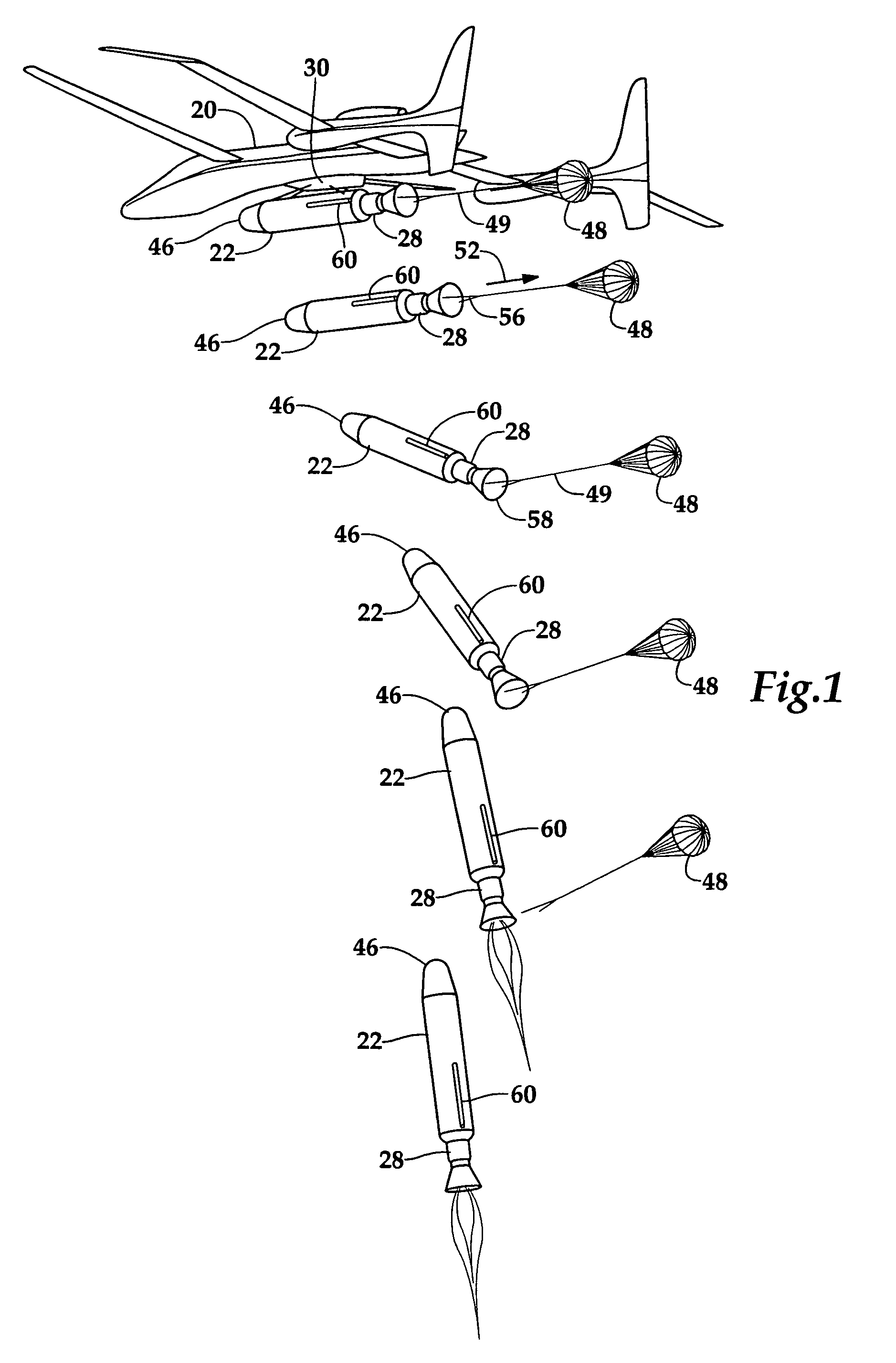
[0015]The drogue parachute which is attached to the rear of the launch vehicle has two main functions in addition to constraining the spindle to the U-shaped slots on the trapeze by producing a rearward force. First it stabilizes the launch vehicle in yaw as it begins to drop down and rearward of the carrier aircraft. Secondly, it is used to progressively reduce the rate of rotation as the launch vehicle moves from a horizontal to a vertical orientation. When the launch vehicle is near the vertical orientation, rotation of the launch vehicle has been substantially reduced by the drogue parachute and the vehicle's rocket engine is ignited. The drogue parachute is then separated from the launch vehicle, and the vehicle begin its powered flight into orbit. By controlling the rate of rotation by adjusting the braking force and length of the lanyard, the distance of the launch vehicle from the carrier aircraft when the launch vehicle reaches a vertical orientation can be controlled. The slower the launch vehicle rotates, the more time that is required for the vehicle to rotate to the vertical orientation.
[0018]It is another object of the present invention to provide an apparatus and method of air dropping a launch vehicle from beneath a carrier aircraft where loads applied to the launch vehicle are minimized.
[0019]It is yet another object of the present invention to provide an apparatus and method for increasing the safety of the carrier aircraft after the release of a launch vehicle.

Problems solved by technology

The result of this negative pressure imbalance is that the vehicle will begin to rotate as it falls away from the carrier aircraft with the possibility that the forward portion will impact the carrier aircraft.
Secondly, it is used to progressively reduce the rate of rotation as the launch vehicle moves from a horizontal to a vertical orientation.

Method used


Image

  • Method and apparatus for dropping a launch vehicle from beneath an airplane
  • Method and apparatus for dropping a launch vehicle from beneath an airplane
  • Method and apparatus for dropping a launch vehicle from beneath an airplane

Examples


Embodiment Construction

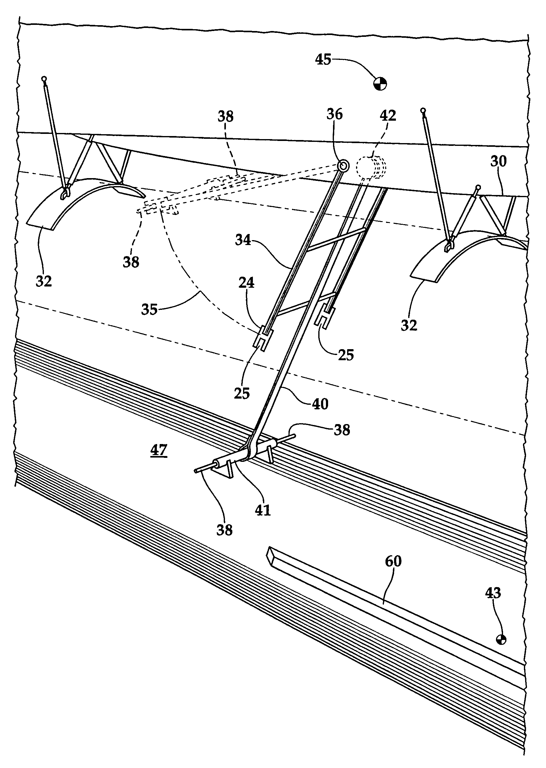
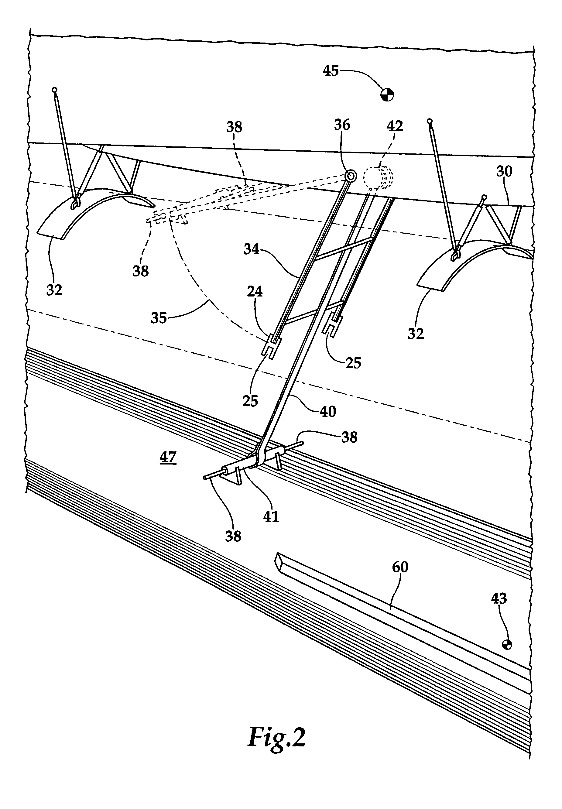
[0024]Referring more particularly to FIGS. 1-3, wherein like numbers refer to similar parts, a launch vehicle 22 is shown carried underneath a carrier aircraft 20. The description, and illustrations are based in part on a drop test article, i.e., the launch vehicle 20 which was used to prove out the concept of the design. The, the launch vehicle 20 drop test article, is a 23 percent scale test article, weighing about 2,000 lb. A preferred embodiment launch vehicle 22 shown in FIG. 3 is a 100 percent scale compared to the drop test article's 23 percent scale, and has a launch weight of more than 300,000 lb, i.e., about 9,000 slugs mass, and could be carried by a Boeing 747 aircraft. Three drop test were preformed with the 23 percent scale launch vehicle 22.

[0025]The launch vehicle 22 was mounted to the carrier aircraft 20 by a release mechanism (not shown) forming part of a bomb rack (not shown) mounted to the carrier aircraft and carried within a pylon 30 extending from the bottom o...


PUM


Abstract

A system for launching a launch vehicles mounted beneath an aircraft. A mechanism which separates the launch vehicle from the carrier aircraft engages the launch vehicle, and prevents the launch vehicle from coming into contact with the carrier aircraft as the launch vehicle is dropped away from the launch vehicle. A lanyard extends from the carrier aircraft applies an impulse to the launch vehicle as it is separated from the aircraft causing the launch vehicle to rotate upwardly of the pitch plane. A drogue parachute applies a rearward force to the launch vehicle holding the rigid trapeze in engagement with the launch vehicle, and damping the rate of rotation in the pitch plane as the rotation of the pitch plane brings a launch vehicle to a substantially vertical launch attitude, were powered flight of launch vehicle is begun. The launch vehicle follows a trajectory that crosses behind the carrier aircraft.

Description

STATEMENT AS TO RIGHTS TO INVENTIONS MADE UNDER FEDERALLY SPONSORED RESEARCH AND DEVELOPMENT[0001]This invention was made with Government support under Agreement No. NNT04AA04C awarded by the National Aeronautics and Space Administration. The Government has certain rights in the invention.CROSS REFERENCES TO RELATED APPLICATIONS[0002]Not applicable.BACKGROUND OF THE INVENTION[0003]The present invention relates to systems for launching a launch vehicle from an aircraft in general, and to vehicles that are air launched captive-on-bottom from a carrier aircraft, in particular.[0004]Rocket launch vehicles, both with and without crews, have conventionally been launched from ground-based installations near coastal areas. These installations have been fixed launch stands, such as Cape Canaveral, or specialized mobile carriers used for missile launches. Ground launches, however, present problems of launch delays due to inclement weather, the necessity to clear the vicinity of air traffic to...

Claims


Application Information

Patent Timeline
Patent Type & Authority Patents(United States)
IPC IPC(8): B64D1/12
CPCB64D1/12B64G1/005
Inventor SARIGUL-KLIJN, MARTISARIGUL-KLIJN, NESRIN
Owner SARIGUL KLIJN MARTI
Learn More