Feed spacer for spiral-wound membrane module

a technology of spiral wound membrane module and feed spacer, which is applied in the field of spacer, can solve the problems of no effort placed, and the outer surface would be expected to have an adverse impact on the performance of the membrane module, and achieve the effect of reducing the diameter of the outer filament and reducing the shear rate differen

Inactive Publication Date: 2008-12-02
CHUNG YUAN CHRISTIAN UNIVERSITY
View PDF7 Cites 17 Cited by
  • Summary
  • Abstract
  • Description
  • Claims
  • Application Information

AI Technical Summary

Benefits of technology

[0007]One object of this invention is to adjust the feed spacer diameter ratio of outer to inner filaments, so as to reduce the shear rate difference between outer and inner surfaces of feed spacer. Results showed that decreasing of the diameter of outer filament can improve the mentioned adverse impact. Another object of this invention is to arrange feed spacer with different filament diameter inside the spiral-wound membrane module, and arrange feed spacer with the same filament diameter outside the spiral wound membrane module, whereupon the shear rate difference between outer and inner surfaces of feed spacer can be controlled according to the relative distance between the feed spacer and the center of the spiral-wound membrane module. Therefore, this present invention does have the economic advantages for industrial applications.

Problems solved by technology

However, no any effort has been placed on the effects of curvature of the spacer and membrane permeability in the spiral-wound modules on the pressure drop, shear rate and separation efficiency through the curved module.
Such unequal shear rates at the inner and outer surfaces would be expected to have an adverse impact on the membrane module performance because of different fouling characteristics for adjacent membrane leaves.

Method used


Image

  • Feed spacer for spiral-wound membrane module
  • Feed spacer for spiral-wound membrane module
  • Feed spacer for spiral-wound membrane module

Examples


first embodiment

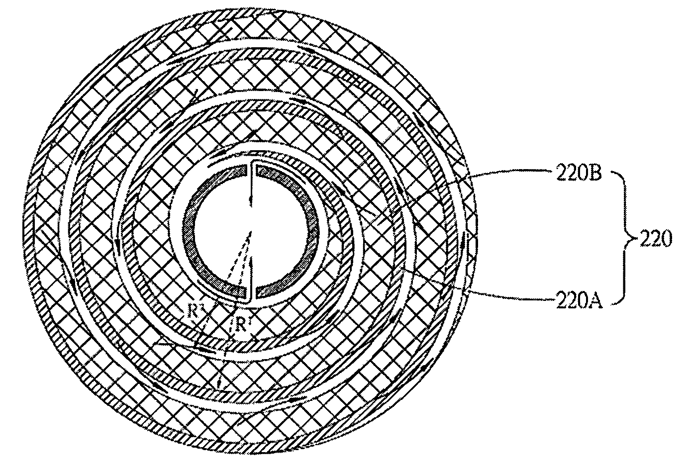
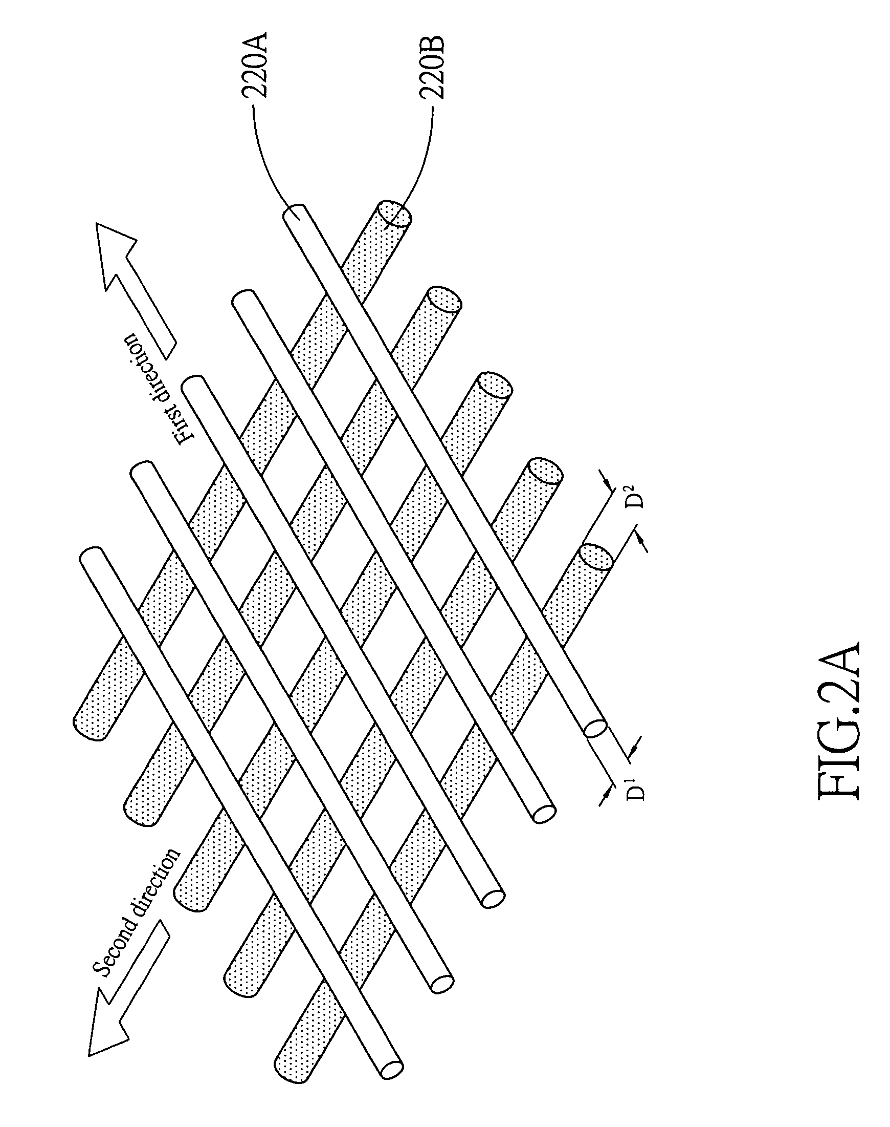
[0015]Referring to FIG. 2A, in the present invention, a feed spacer 220 for spiral-wound membrane module is disclosed, wherein the feed spacer 220 comprises a first layer 220A and a second layer 220B. The mentioned first layer 220A consists of a plurality of first filaments with first diameter D1, wherein the first filaments are substantially in parallel to one another, and are arranged along a first direction. The mentioned second layer 220B consists of a plurality of second filaments with second diameter D2, wherein the second filaments are substantially in parallel to one another, and are arranged along a second direction. Furthermore, a top view of FIG. 2A is shown in FIG. 2B, wherein the first layer 220A is attached to the second layer 220B, the angle between the first direction and the second direction ranges from 60° to 120°, and the preferred angle is 80°. Additionally, referring to FIG. 2C, both the first layer 220A and the second layer 220B bend to the center of the spiral...

second embodiment

[0016]Referring to FIG. 3, in the present invention, a feed spacer 320 for spiral wound is disclosed, wherein the feed spacer 320 comprises a first layer 320A and a second layer 320B. The mentioned first layer 320A consists of a plurality of first filaments with first diameter D1, wherein said plurality of first filaments are substantially in parallel to one another, and are arranged along a first direction. The mentioned second layer, consisting of a plurality of second filaments with second diameter D2, wherein said plurality of second filaments are substantially in parallel to one another, and are arranged along a second direction. Furthermore, the first layer 320A is attached to the second layer 320B, the angle between the first direction and the second direction ranges from 60° to 120°, and the preferred angle is 80°. Both the first layer 320A and the second layer 320B bend to the center of the spiral-wound. Additionally, R is defined as the diameter of the spiral-wound membran...


PUM

PropertyMeasurementUnit
angleaaaaaaaaaa
angleaaaaaaaaaa
diameter D1aaaaaaaaaa

Abstract

The present invention discloses a feed spacer, comprising a first layer and a second layer, for spiral-wound membrane module. The first layer consists of a plurality of first filaments, which are substantially in parallel to one another. Furthermore, the second layer also consists of a plurality of second filaments, which are substantially in parallel to one another. Moreover, the first layer is attached to the second layer, and the first filaments are disposed at an angle to the second filaments. Both the first layer and the second layer bend to the center of the spiral-wound. Additionally, the distance from the inside of the first layer to the center is bigger than that from the inside of the second layer to the center, and the diameter of the first filament is smaller than that of the second filament.

Description

BACKGROUND OF THE INVENTION[0001]1. Field of the Invention[0002]The present invention is generally related to a spacer, and more particularly to a feed spacer for spiral-wound membrane module.[0003]2. Description of the Prior Art[0004]Membrane filtration procedures are well applied in industries. Therefore, various filtration membrane apparatus are designed and manufactured. For example, spiral wound membrane module is used in cross-flow filtration, and the advantages of spiral wound membrane module are smaller size, greater filtration area, and higher shear rate. A cross-sectional view of a conventional spiral wound membrane module is shown in FIG. 1, wherein the spiral wound membrane module comprises an outer cover 110, feed spacer 120, permeate spacer 130 and permeate collection tube. Besides, arrows 150 indicate the flow direction of permeate. The filtration membranes are in planar contact with the outer surface and the inner surface of the feed spacer. Furthermore, the feed spa...

Claims


Application Information

Patent Timeline
Patent Type & Authority Patents(United States)
IPC IPC(8): B01D63/10
CPCB01D63/10
Inventor TUNG, KUO-LUNLI, YU-LINGLU, MING-YANGLAI, JUIN-YIH
Owner CHUNG YUAN CHRISTIAN UNIVERSITY
Why Eureka
Try Eureka