Switchgear device comprising an arc chute of reduced size

a technology of arc chute and switchgear, which is applied in the direction of air-break switch, high-tension/heavy-dress switch, electrical apparatus, etc., can solve the problem of not being able to adapt to switchgear devices, and achieve the effect of reducing siz

Active Publication Date: 2008-12-02
SCHNEIDER ELECTRIC IND SAS
View PDF10 Cites 6 Cited by
  • Summary
  • Abstract
  • Description
  • Claims
  • Application Information

AI Technical Summary

Benefits of technology

[0008]The object of the invention is therefore to remedy the shortcomings of the state of the art so as to propose an arc chute of reduced size enabling the arc to be extinguished at the moment breaking of low-intensity currents is performed under high voltages.

Problems solved by technology

However the solution of the Patent FR2803687 can not be adapted to switchgear devices the arc chute whereof also has to be reduced in width while keeping the same proportions in the other directions.

Method used


Image

  • Switchgear device comprising an arc chute of reduced size
  • Switchgear device comprising an arc chute of reduced size
  • Switchgear device comprising an arc chute of reduced size

Examples


Embodiment Construction

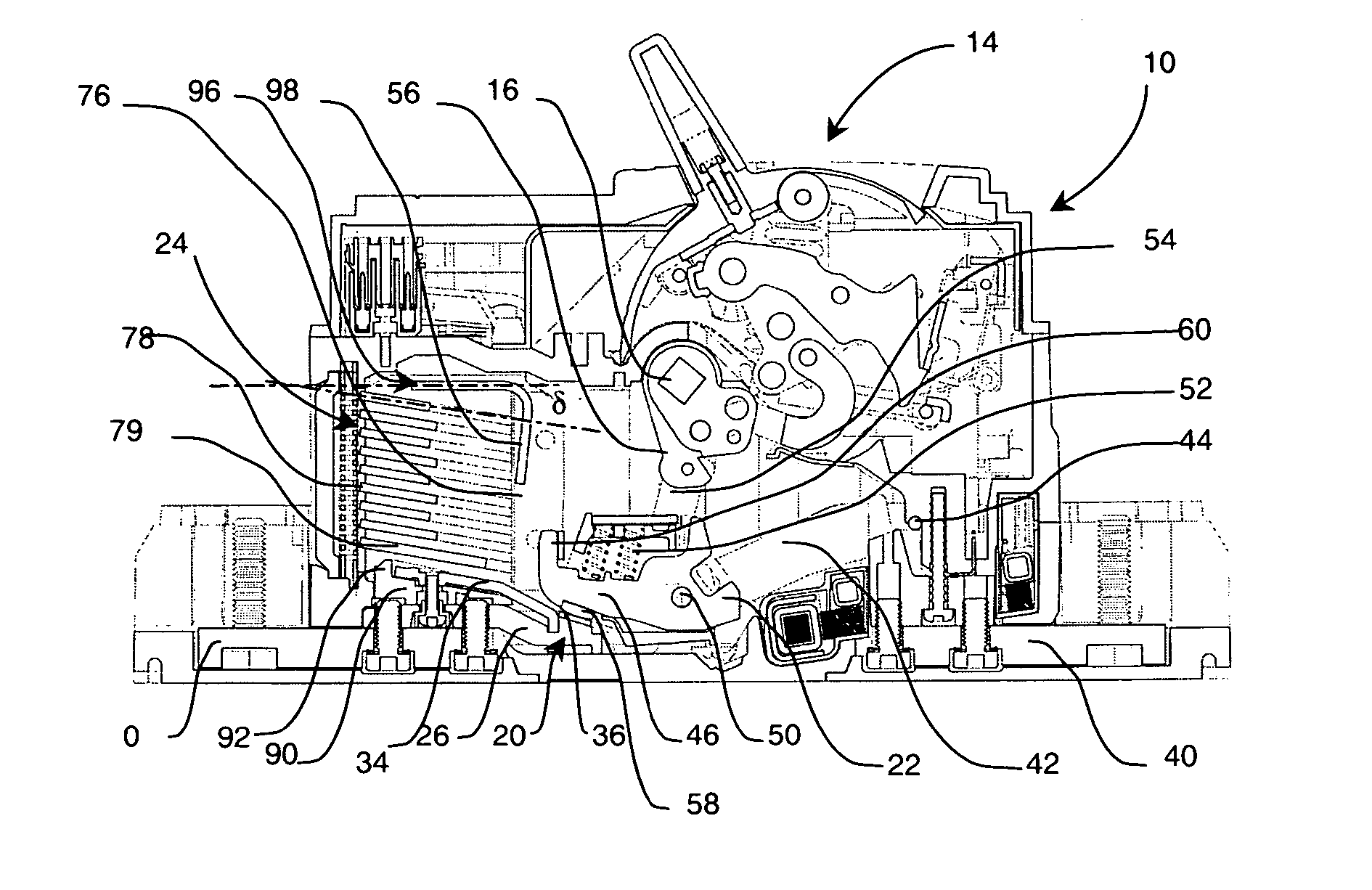
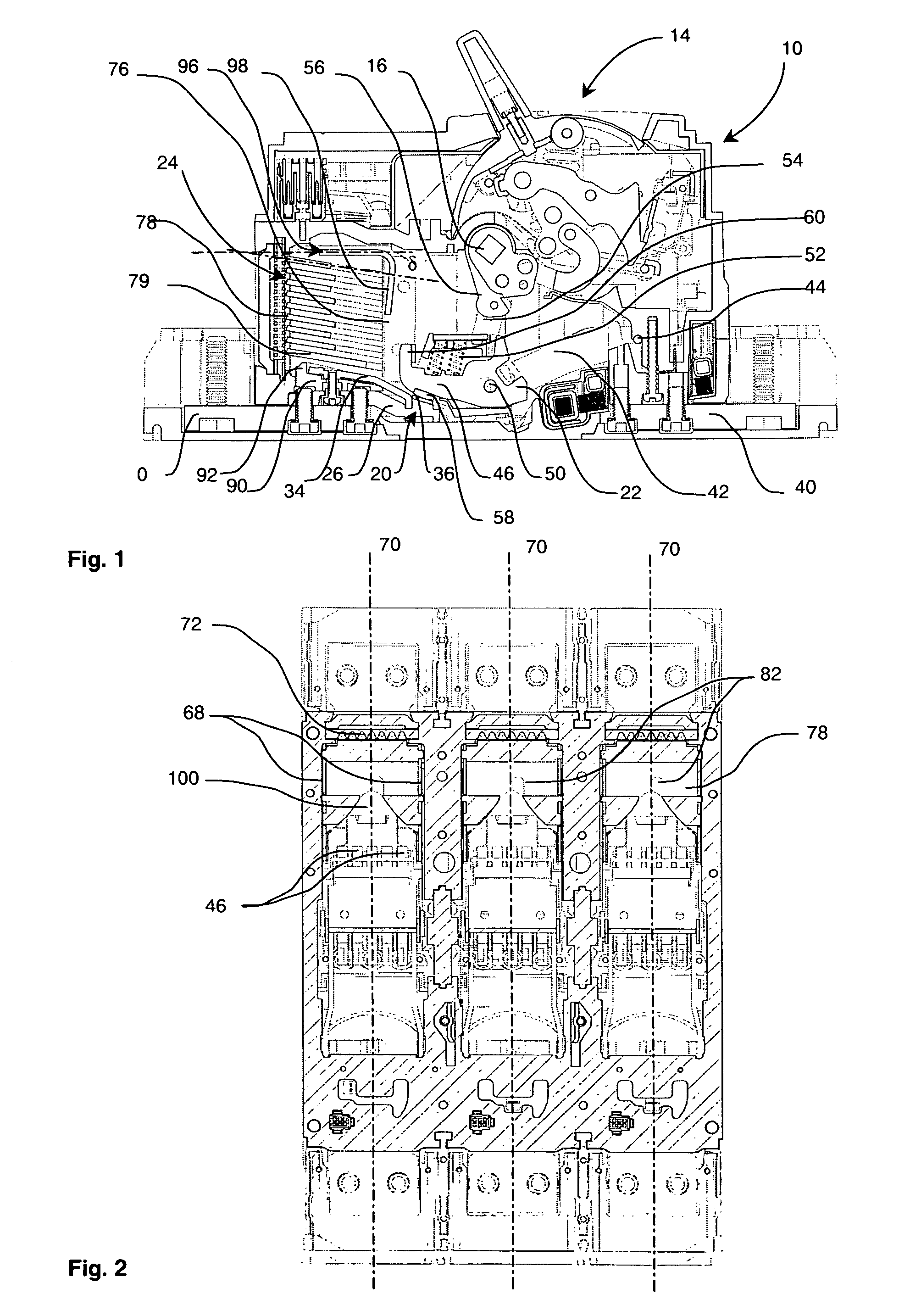
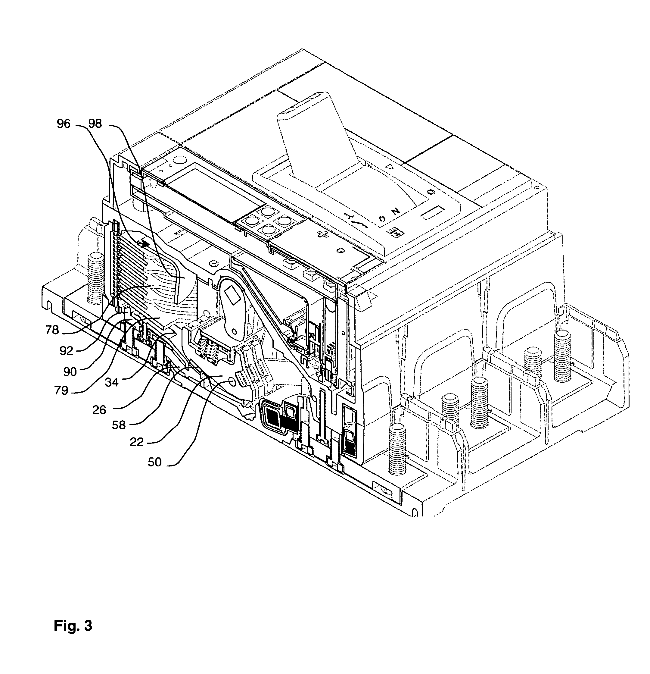
[0029]According to the preferred embodiment of the invention, with reference to FIGS. 1 to 3, a multipole low-voltage power switchgear device 10 comprises a moulded insulating case 12 housing an operating mechanism 14 of known type equipped with a transverse switching bar 16 common to all the pole-units, swivel-mounted in bearings arranged in the case 12. Each pole-unit comprises a stationary contact part 20, a movable contact part 22 and an arc chute 24 located close to the stationary contact part 20.

[0030]The stationary contact part 20 comprises a current input terminal 26 fitted in the bottom of the case 12, partially under the arc chute 24. The stationary current input terminal 26 comprises a contact strip 36 that operates in conjunction with contact pads 58 of the contact fingers 46 of the movable contact part 22. The contact fingers 46 are electrically connected to the current input terminal 40 by means of a tunnel 42.

[0031]The stationary current input terminal 26 is extended ...


PUM


Abstract

Electric switchgear device comprising at least one electric pole-unit comprising a stationary contact part made of conducting material, a movable contact part and an arc chute. The arc chute comprises two side parallel flanges, a rear wall, and a bottom arcing horn made of conducting material, electrically connected to the stationary contact part. Said bottom arcing horn is surrounded by a periphery made of gas-generating material. The arc chute comprises a stack of separators at least two of which separators comprise a notch. The arc chute comprises at least one regenerating separator placed parallel to the bottom arcing horn, said at least one separator comprising at least one metallic surface covering at least half of the notches in the longitudinal mid-plane.

Description

BACKGROUND OF THE INVENTION[0001]The invention relates to an electric switchgear device comprising at least one electric pole-unit comprising a stationary contact part made of conducting material, a movable contact part able to move from a closed position wherein it is in contact with the stationary contact part to an open position wherein the two contact parts are separated. The electric switchgear device comprises an arc chute comprising two parallel side flanges placed on each side of a longitudinal mid-plane, a rear wall, a bottom arcing horn made of conducting material connected to the stationary contact part and extending close to the rear wall. Said bottom arcing horn is surrounded by a periphery made of gas-generating material. The arc chute comprises a stack of separators extending from one side flange to the other, substantially perpendicularly to the longitudinal mid-plane, at least two of the separators comprising a notch extending in the longitudinal mid-plane.STATE OF ...

Claims


Application Information

Patent Timeline
Patent Type & Authority Patents(United States)
IPC IPC(8): H01H33/02
CPCH01H9/36H01H9/46
Inventor RIVAL, MARC
Owner SCHNEIDER ELECTRIC IND SAS
Why Eureka
Try Eureka