Multiple frequency through-the-wall motion detection and ranging using a difference-based estimation technique

a technology of difference-based estimation and through-the-wall motion detection, which is applied in the field of through-the-wall sensors, can solve the problems of insufficient information for individuals, single-frequency radars that cannot permit the detection of range to the moving individual, and require fairly expensive hardware, so as to increase the resolution of the subject system, and reduce the size of the range cell.

Inactive Publication Date: 2008-12-02
BAE SYST INFORMATION & ELECTRONICS SYST INTEGRATION INC
View PDF14 Cites 31 Cited by
  • Summary
  • Abstract
  • Description
  • Claims
  • Application Information

AI Technical Summary

Benefits of technology

[0016]Thus, it is possible to determine range to the motion even if the motion is not constant or the target moves only a fraction of the carrier wavelength
[0028]Having ascertained the range cell that all activity is in, one can increase the resolution of the subject system by increasing the separation between the two tones to decrease the range cell size and thus increase the resolution.
[0029]More particularly, this system detects not only motion in a room but also the range of the moving object. One wants to know and locate where in the building the moving object is. If one is able to measure range, this aids in that process of locating individuals in a room or behind a wall.

Problems solved by technology

However, the use of a single frequency radar does not permit the detection of range to the moving individual and may provide less-than-adequate information to individuals, for instance when trying to detect the whereabouts of a moving individual behind a wall.
The difficulty with ultra wideband approaches is that one has to generate short pulses, which requires fairly expensive hardware.
A particular difficulty with ultra wideband is that walls have frequency-dependent attenuation.
This results in a distortion of the return pulses that pass through the wall.
This distortion blurs the pulse, making it hard to correlate.
The problem with generating streams of pulses is the existence of clutter and with an ultra wideband pulsed radar, one detects everything within a room.

Method used


Image

  • Multiple frequency through-the-wall motion detection and ranging using a difference-based estimation technique
  • Multiple frequency through-the-wall motion detection and ranging using a difference-based estimation technique
  • Multiple frequency through-the-wall motion detection and ranging using a difference-based estimation technique

Examples


Embodiment Construction

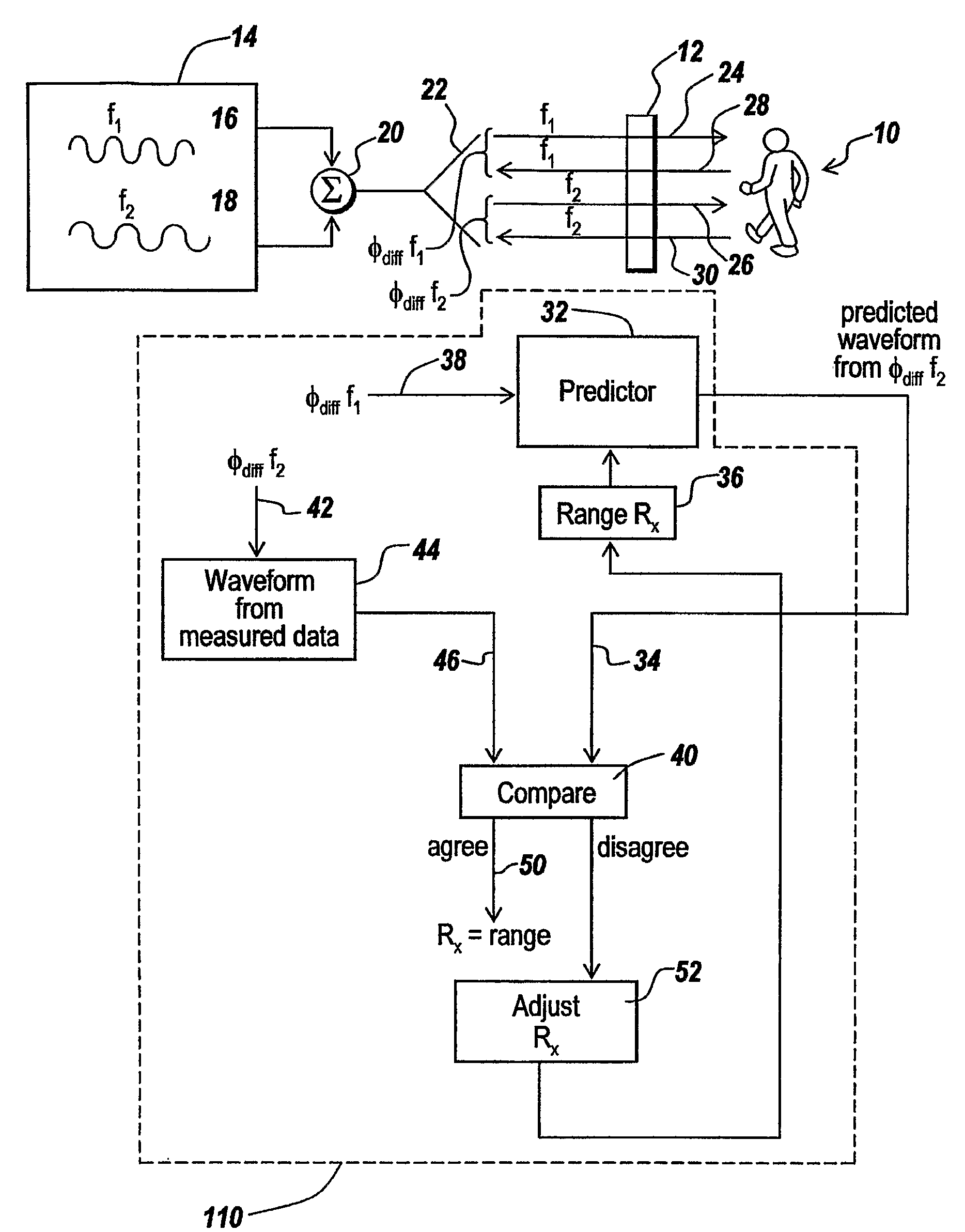
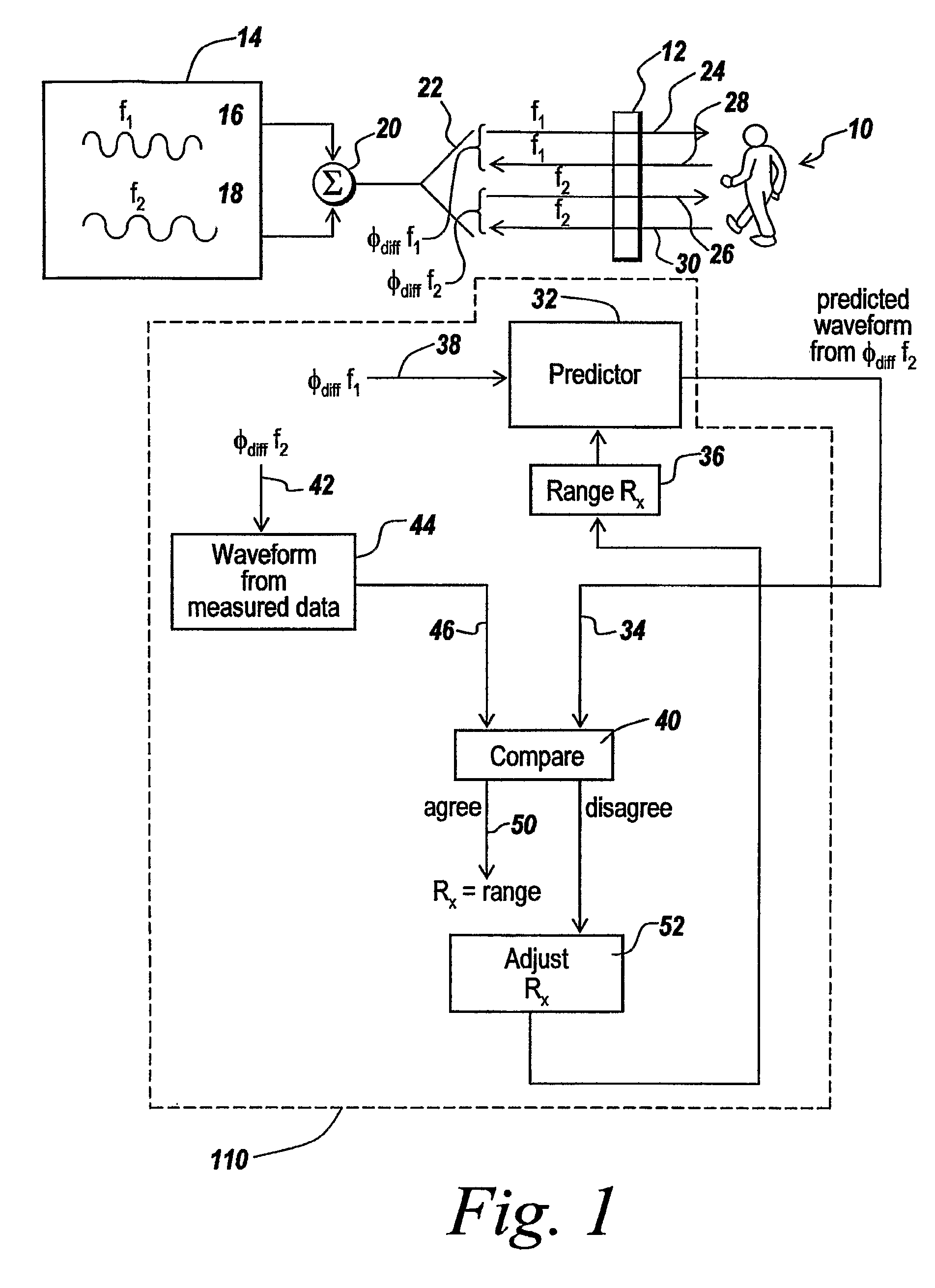
[0041]Referring now to FIG. 1, in order to detect the presence of an individual 10 constituting a moving object behind a wall 12, a radar 14 is provided, which transmits continuous waves 16 and 18 through a summation device 20 to an antenna 22. Antenna 22 simultaneously projects the two waveforms at f1 and f2 as illustrated at 24 and 26 through wall 12, where they meet object 10 and are reflected backwardly as illustrated at 28 and 30. The phase difference between outgoing and incoming waveforms for each of the frequencies is detected as will be discussed, and in one embodiment the waveform corresponding to the temporal phase difference for tone f1 is coupled to a predictor 32. It is the purpose of predictor 32 to predict the temporal waveform that would be expected to exist for the temporal phase difference waveform at frequency f2 for an object at a known distance or range, with the output of the predictor being a waveform on line 34. In order for predictor 32 to operate, the pred...


PUM


Abstract

A multi-tone CW radar (14) is used to project signals from an antenna (22) and to receive returns with the same antenna. The phase differences between the outgoing signals and the returns are analyzed to determine the existence of motion and the range to a moving object (10). A model is made which has range as its major parameter. A waveform associated with the phase difference between outgoing signals and returns for one of the tones is compared to templates produced by the model to determine which has a range that most closely matches. By varying the range parameters, when a match is detected the range to the object can be obtained even if its motion is pseudorandom. If the range is measured with multiple units it is possible to measure the location of the object. This can be done assuming a grid and algorithmically combining the ranges from the units.

Description

RELATED APPLICATIONS[0001]This application claims rights under 35 USC § 119(e) from U.S. Provisional Application Ser. No. 60 / 537,868 filed Jan. 20, 2004, the contents of which are incorporated herein by reference.FIELD OF THE INVENTION[0002]This invention relates to through-the-wall sensors and more particularly to the use of a two-tone CW radar to detect both motion and range of objects behind a wall.BACKGROUND OF THE INVENTION[0003]As described in PCT Patent Application PCT / US04 / 30116 filed Sep. 14, 2004 by Paul Zemany and Eldon Sutphin, a system is described for projecting continuous wave radar energy through a wall to be able to detect motion of persons behind the wall. In the invention described above, motion is detected by a change in the phase difference between the transmitted wave and the received wave, which is indeed sensitive in detecting motion.[0004]However, the use of a single frequency radar does not permit the detection of range to the moving individual and may prov...

Claims


Application Information

Patent Timeline
Patent Type & Authority Patents(United States)
IPC IPC(8): G01S13/50G01S13/62
CPCG01S13/38G01S13/888
Inventor ZEMANY, PAUL D.SUTPHIN, ELDON M.
Owner BAE SYST INFORMATION & ELECTRONICS SYST INTEGRATION INC
Why Eureka
Try Eureka