Color separation table generation method and image processing apparatus

Inactive Publication Date: 2008-12-02
CANON KK
View PDF13 Cites 13 Cited by
  • Summary
  • Abstract
  • Description
  • Claims
  • Application Information

AI Technical Summary

Benefits of technology

[0020]According to the above configuration, when generating a color separation table, the point of a special color other than colors corresponding to the vertexes of the cube is set on a side of the cube, which connects two vertexes of the cube corresponding to the color separation table defined by input colors Then based on the color measurement of predetermined patches, grid point data is obtained for grid points on each of a line connecting two vertexes of black and white on the cube, a line running on the surface of the cube and connecting a plurality of vertexes of the cube, and a line running on the surface of the cube and connecting a plurality of the vertexes of the cube as well as the point of the special color. Then the cube is divided

Problems solved by technology

However, according to the method disclosed in the above document, it may not be possible to generate an appropriate color separation table when using, for example, the printing material of orange as the special color, other than red, green and blue that are secondary colors of cyan, magenta and yellow.
However, such a special color as orange is not a color that exists at any vertexes of the cube As a result, if the method disclosed in Japanese Patent Application Laid-open No. 2002-033930 is used when orange is used as a s

Method used


Image

  • Color separation table generation method and image processing apparatus
  • Color separation table generation method and image processing apparatus
  • Color separation table generation method and image processing apparatus

Examples


embodiment 1

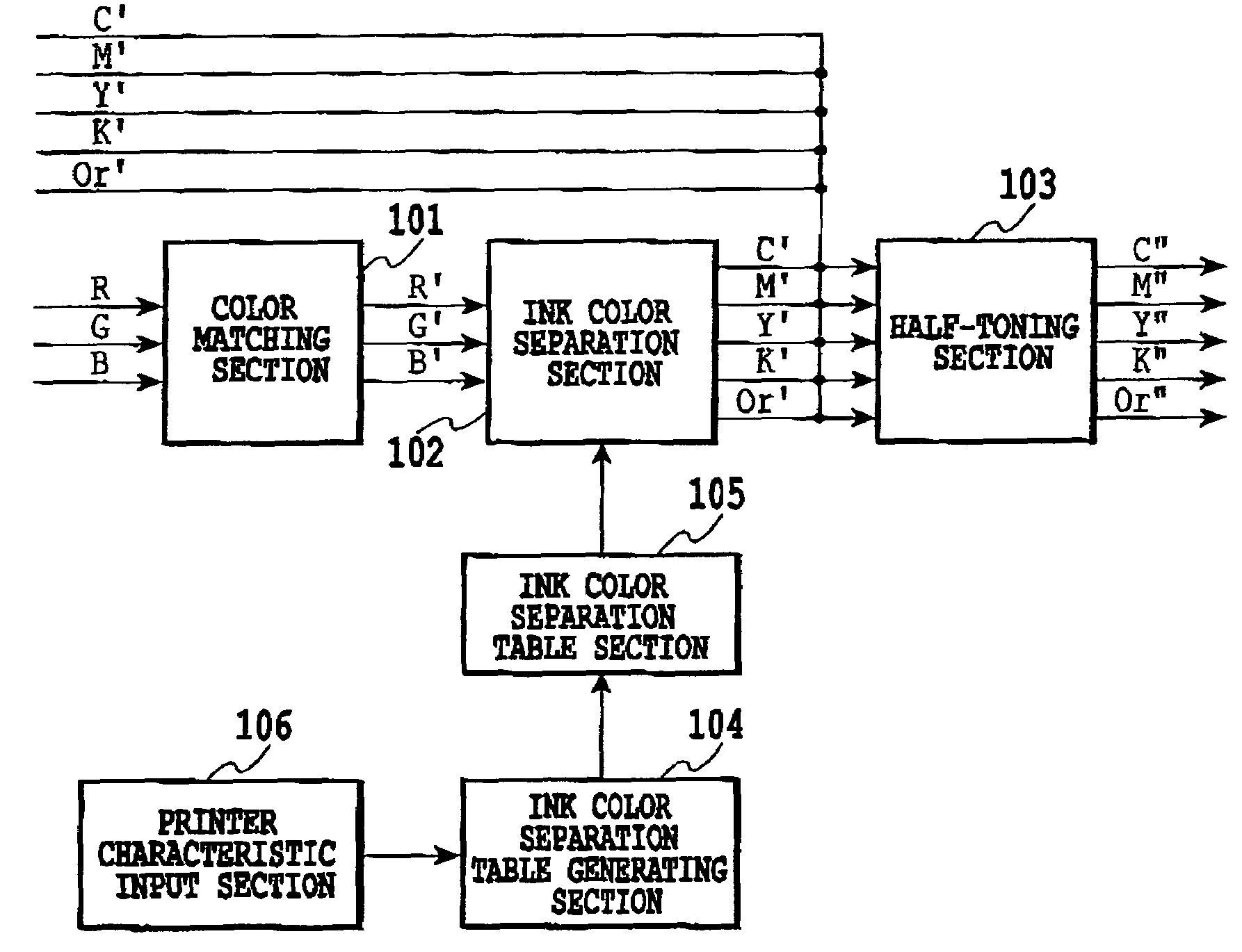
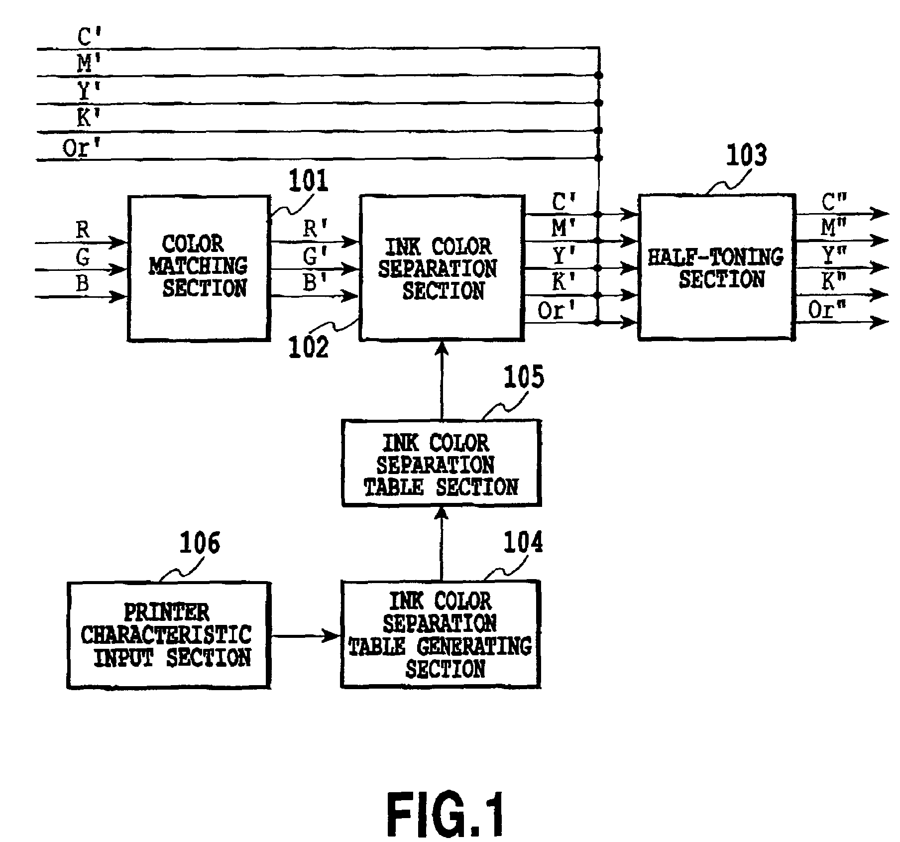
[0049]FIG. 1 is a block diagram briefly illustrating the configuration for executing a color separation process and generation of a color separation table in a printing system of an embodiment of the invention.

[0050]In the figure, denoted 101 is a color matching section that matches the color reproduction property of RGB with the colors reproduced by a printer, 102 is an ink color separation section that converts R′, G′, B′ multi-value data outputted from the color matching section into colors of printing materials C′ (cyan), M′ (magenta), Y′ (yellow), K′ (black) and a special color Or′ (orange) in the printer, and 103 is a half-toning processing section that converts the C′, M′, Y′, K′ and Or′ multi-value data outputted from the ink color separation section 102 into a gradation value (for example, binary value) which the printer can realize.

[0051]Denoted 105 is an ink color separation table section that provides a lookup table (LUT) to the ink color separation section 102 for using...

embodiment 2

[0148]In the above embodiment, five colors C, M, Y, K and or are exemplified as printer ink colors. For the seven-color printer using light cyan and light magenta in addition to such five colors, an interpolation similar to the above embodiment can be made only by adding two ink colors.

[0149]Furthermore, when special colors red (R), green (G) and blue (B) other than Or are employed, points RM between R and M, RY between R and Y, GY between G and Y, and GC between G and C are set as shown in FIG. 26. When using such secondary colors, the above enlargement and reduction described in the embodiment makes internal interpolation easy.

embodiment 3

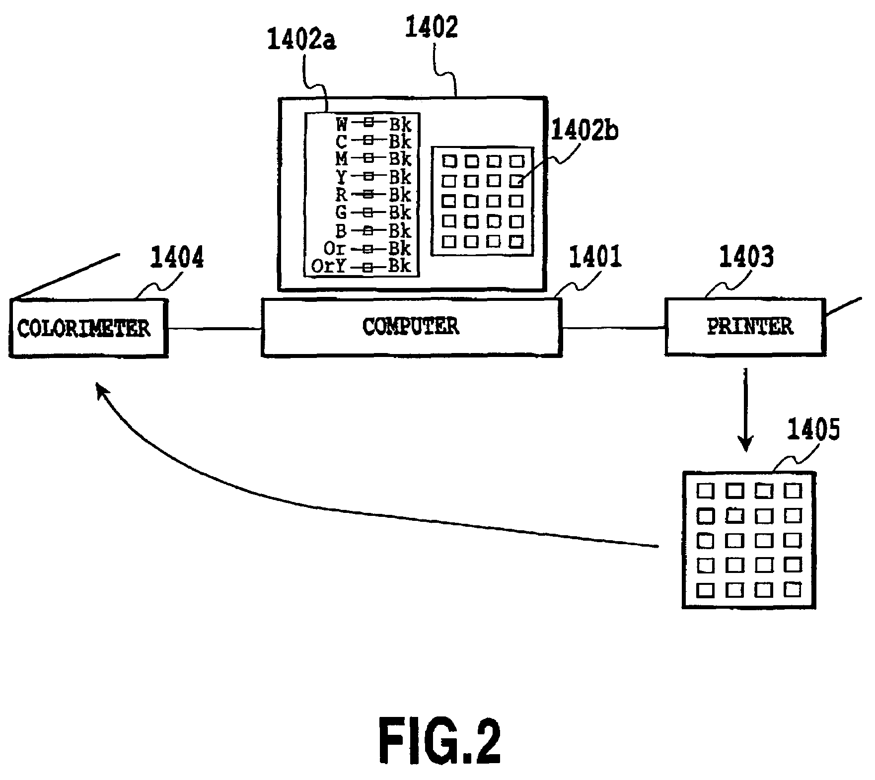
[0150]The above embodiment has described an example in which the color separation table generated with a computer is downloaded to the printer and the controller in the printer carries out the color separation process. However, the invention can be applied to other cases; for example, the invention can be applied to such a case where the color separation table generated in the computer 1401 of FIG. 2 is set to the LUT in the printer driver.


PUM


Abstract

When a special color, which is a color other than the vertexes of the RGB cube during the generation of a color separation table, is used as an ink color, the invention sets a grid point for the special color on a side connecting cube vertexes. Then it becomes possible, by determining in advance grid point data based on a color measurement on the line including the grid point of the special color, to prepare a color conversion table having a uniform grid point density in the uniform color space even when a special color other than red, green and blue is used.

Description

[0001]This application claims priority from Japanese Patent Application No. 2002-344508 filed Nov. 27, 2002, which is incorporated hereinto by reference.BACKGROUND OF THE INVENTION[0002]1. Field of the Invention[0003]The invention relates to a color separation table generation method and image processing system, and more particularly, to generating a color separation table that converts color signals forming image data into color signals of printing materials such as inks used In printing.[0004]2. Description of the Related Art[0005]In a process of converting color signals of image data into color signals of printing materials such as inks used in a printing apparatus such as a color printer (hereinafter, called the ink color separation process), it is a usual practice to use a color separation table. As an example of methods of generating a color separation table, the technique described in Japanese Patent Application Laid-open No. 2002-33930 is well known. In general, the color se...

Claims


Application Information

Patent Timeline
IPC IPC(8): G03F3/00G03F3/10G06T1/00B41B1/00B41J1/00G06F15/00G06K1/00H04N1/46H04N1/54H04N1/60
CPCH04N1/54H04N1/6025
Inventor SAITO, KAZUHIRO
Owner CANON KK
Why Eureka
Try Eureka