
Color mixing using the reflective properties of oleds

a technology of reflective properties and oleds, applied in the field of color mixing using the reflective properties of oleds, can solve the problems of non-radiative mechanisms, difficult manufacturing of oleds, and certain challenges, and achieve the effect of effective tuning the color of the combined light emitted

Inactive Publication Date: 2013-09-12
GE LIGHTING SOLUTIONS LLC
View PDF2 Cites 14 Cited by
  • Summary
  • Abstract
  • Description
  • Claims
  • Application Information

AI Technical Summary

Benefits of technology

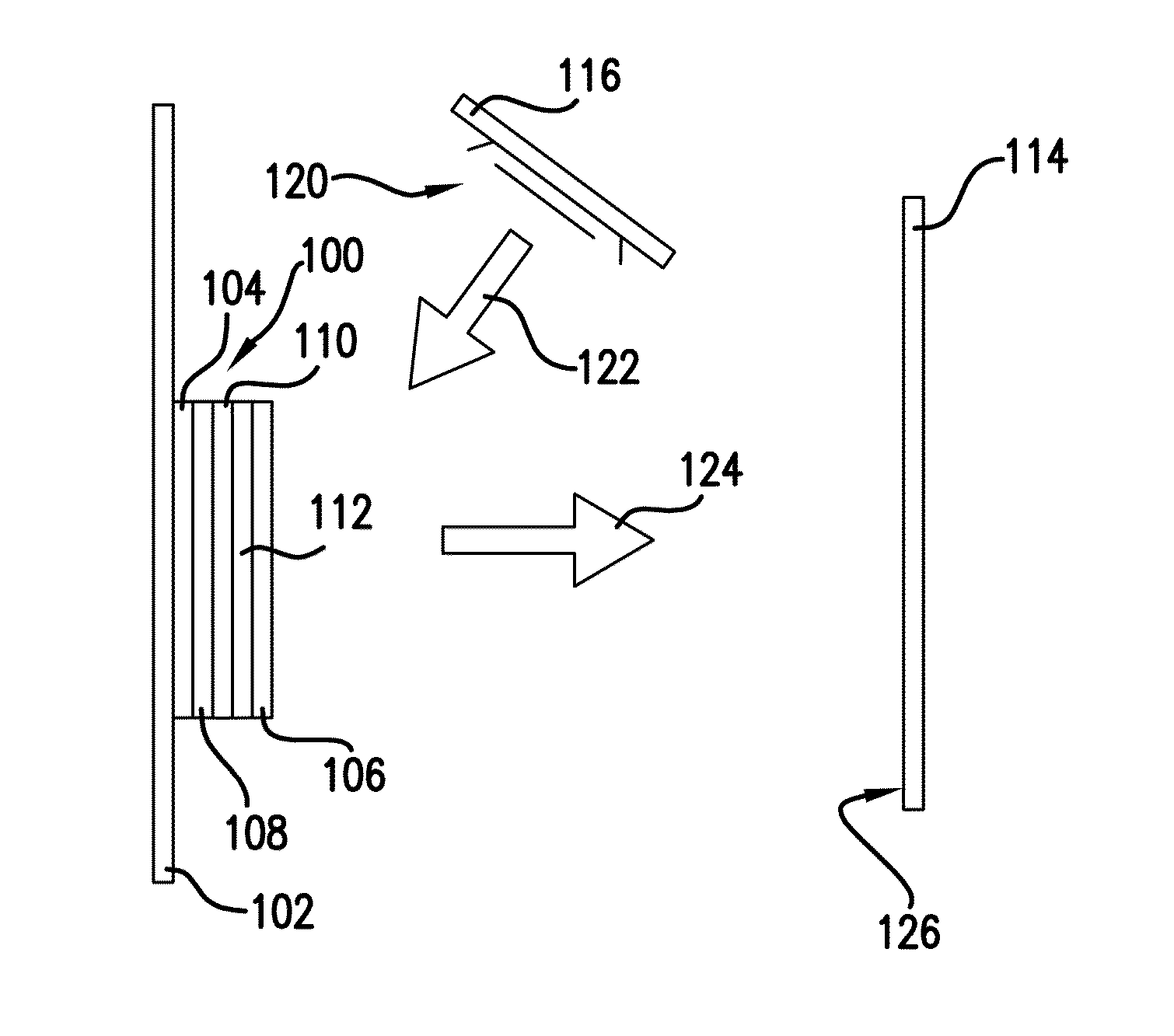
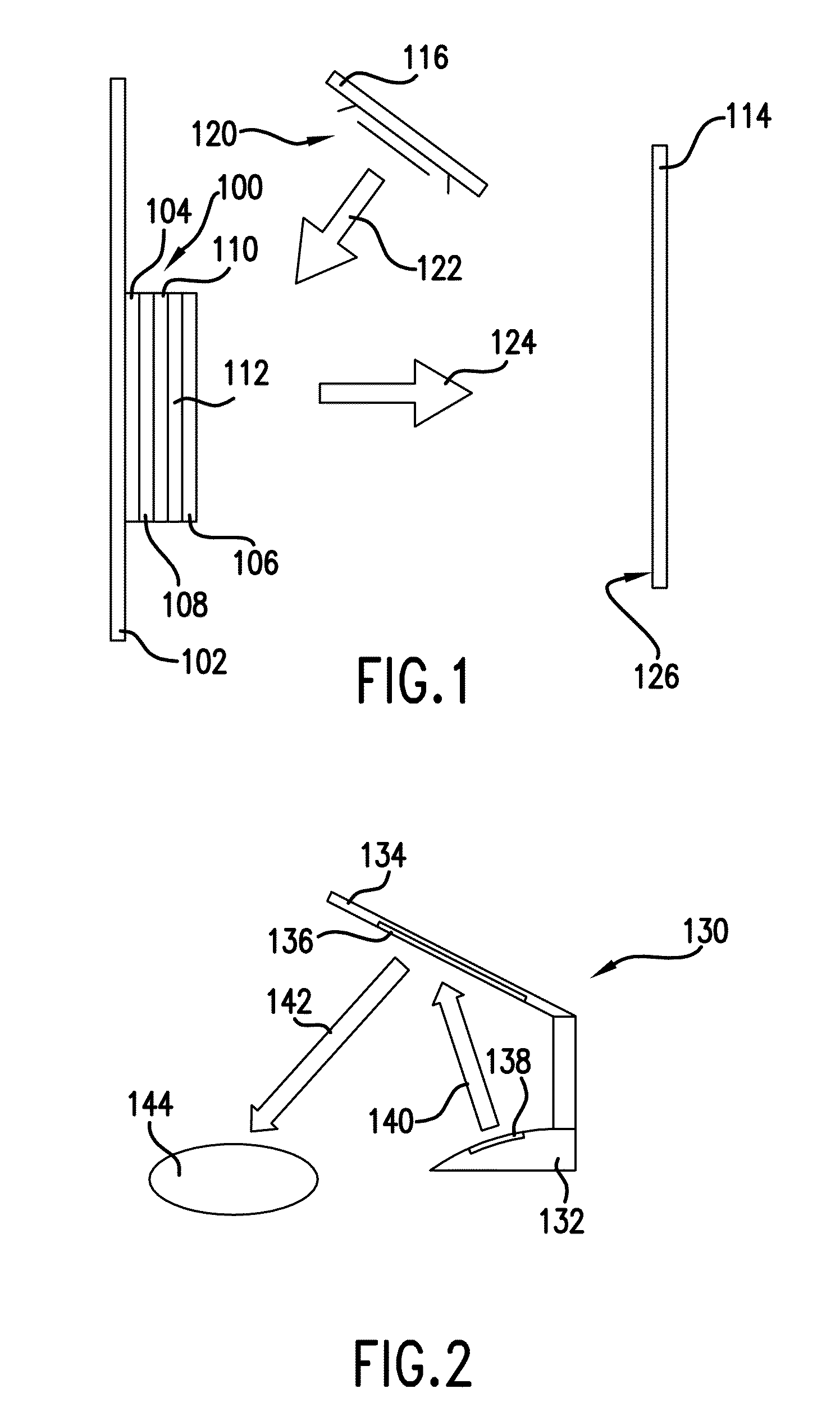
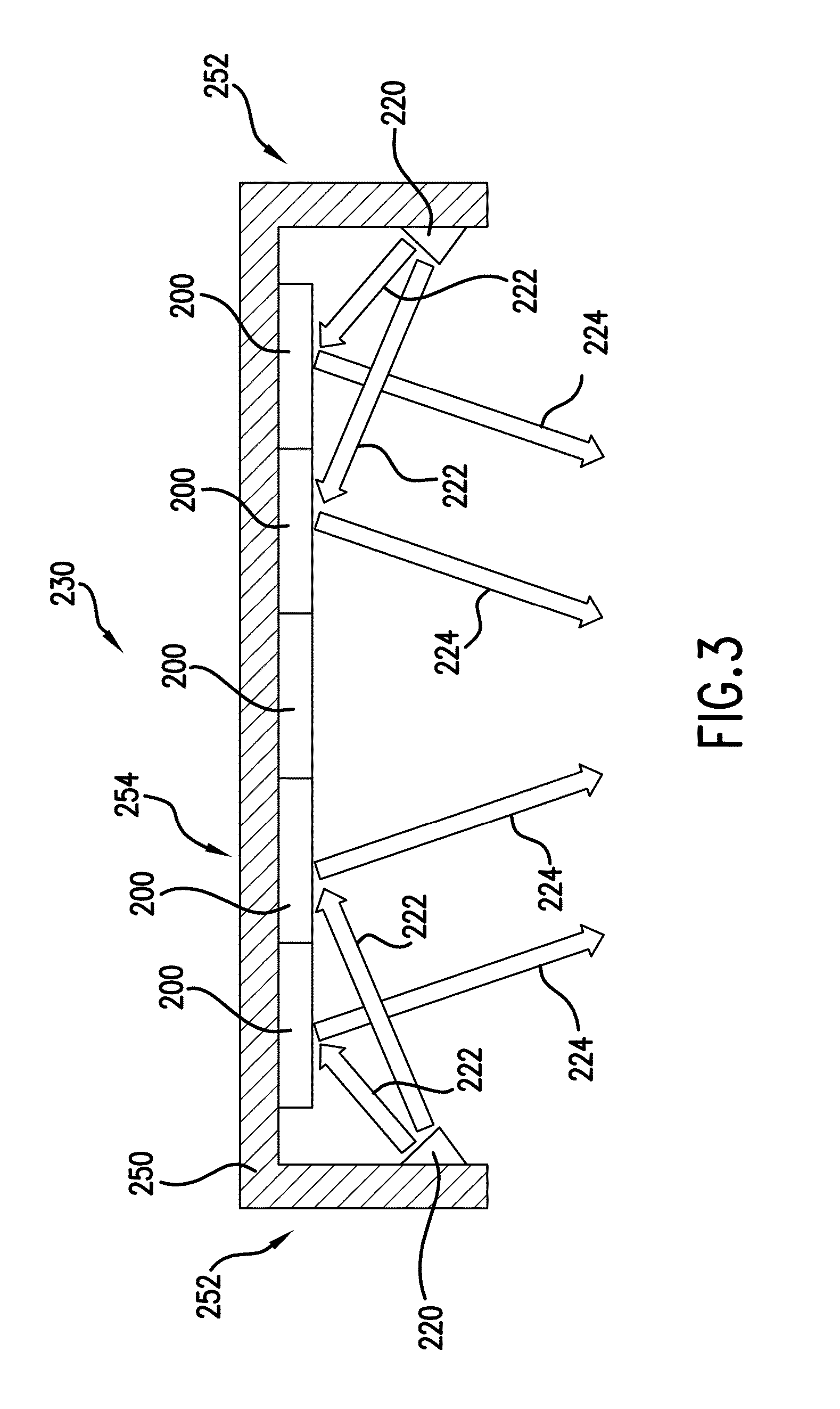
This patent is about a color-tunable light device that includes a primary substrate and two light sources. The first source provides a first light color, the second source provides a second light color, and the second source includes an OLED with a reflective surface. By directing the first light towards the reflective surface of the OLED, a third light color can be achieved. The intensity of the first and second light can be adjusted to effectively tune the combined light emitted from the reflective surface. This technology allows for the creation of a device that can emit different light colors by adjusting the intensity of two light sources.

Problems solved by technology

Non-radiative mechanisms, such as thermal relaxation, may also occur, but are generally considered undesirable.
Certain challenges exist, however, with the manufacture and use of OLEDs.
It is very challenging to manufacture OLEDs of various CCT that have the desired performance characteristics described above, e.g. high brightness, high efficiency, long life, etc.
There have been demonstrations of individually colored OLEDs of red, green, and blue having extremely long life and high efficiency but when trying to combine them into a single white light source the performance characteristics often drop significantly.
As such, when trying to make an OLED with multiple emitters to generate a white light source, it is difficult to optimize and achieve the same performance characteristics of individually colored OLEDs that could have their emitted light mixed to achieve the same color.
Due to the complex energy transfer mechanisms involved in white OLEDs that contain multiple dyes, one cannot simply change the relative concentrations of the dyes to achieve a different CCT of white light.

Method used


Image

  • Color mixing using the reflective properties of oleds
  • Color mixing using the reflective properties of oleds
  • Color mixing using the reflective properties of oleds

Examples


example

[0043]A first white OLED was positioned 27 cm from a white surface and operated with a 50 mA drive current while directed toward the white surface. A second blue OLED was positioned 10 cm away from the first white OLED and directed so as to illuminate the first white OLED and reflect off of the first white OLED towards the white surface. A Radiant Imaging camera was positioned normal to the white surface. Table I shows the measurement results with only the first white OLED activated while Table II shows the results with both OLEDs activated to provide a combined light directed towards the white surface.

TABLE ILuminanceCCT(cd / m2)ccxccy(K)7.890.4160.4293562

TABLE IILuminanceCCT(cd / m2)ccxccy(K)9.790.3530.4154927

[0044]As indicated by the results, the light incident on the white surface is well mixed with a resulting shift in color coordinates—indicating that light from the second blue OLED has reflected off the first white OLED and mixed with light from the first white OLED to provide a ...


PUM


Abstract

Color mixing using the reflective properties of an OLED is provided. At least one OLED is used to reflect light from at least one other light source such that light from the OLED and the additional light source are combined. Light from the additional light source is reflected from a surface in the OLED provided by e.g., the cathode of the OLED. By carefully selecting the individual light colors of the OLED and the additional light source, their combined light can provide a light color different from either the OLED or the additional light source alone.

Description

FIELD OF THE INVENTION[0001]The subject matter of the present disclosure relates generally to color mixing using the reflective properties of OLEDS.BACKGROUND OF THE INVENTION[0002]An organic light-emitting diode device, also called an OLED, commonly includes an anode, a cathode, and an organic electroluminescent unit sandwiched between the anode and the cathode, all of which is disposed on a substrate. The substrate is often made from a transparent material such as plastic or glass. The organic electroluminescent unit generally includes a hole-transporting layer, a light-emitting layer, and an electron-transporting layer, among others. A power source is attached to the anode and cathode. OLEDs are attractive as a light source in lighting applications because of e.g., their low drive voltage, high efficiency, high luminance, long life, thin profile, large-area diffuse light emission, and ability to be shaped into a curved configuration if disposed on a flexible substrate.[0003]When ...

Claims


Application Information

Patent Timeline
Patent Type & Authority Applications(United States)
IPC IPC(8): F21V9/00H05B44/00
CPCH01L25/048H01L51/5036H01L2251/5361Y02B20/36F21Y2113/005F21S8/04F21V7/0008F21Y2105/008F21S6/002H01L2924/0002F21Y2105/00F21Y2115/10F21Y2115/15F21Y2113/13F21Y2113/20Y02B20/30H10K59/90H10K50/125H01L2924/00
Inventor AURONGZEB, DEEDER MOHAMMADKOSTKA, JAMES MICHAEL
Owner GE LIGHTING SOLUTIONS LLC
Learn More