Image display apparatus, and transmissive screen and reflecting mirror used for same

a technology of image display and mirror, which is applied in the field of image display apparatus and transmissive screen and reflecting mirror used for same, can solve the problems of difficult to reduce the thickness of the set, the fresnel lens, and the inability to change the reflected beam into parallel beams,

Inactive Publication Date: 2008-12-02
MAXELL HLDG LTD
View PDF8 Cites 9 Cited by
  • Summary
  • Abstract
  • Description
  • Claims
  • Application Information

AI Technical Summary

Benefits of technology

[0008]It becomes possible to thin down a set by shifting the optical-axis center of a projection lens from the center of a transmissive screen. In this configuration, however, the set increases in height, as shown in FIG. 1 of Patent Reference 1 or FIG. 1 of Patent Reference 2. To reduce the height of the set, it is valid to use a wider-angle projection lens and shorten its projection distance, which makes the set difficult to reduce in thickness; however. In other words, reducing the height of the set and thinning it down are contradictory to each other, and realizing both at the same time becomes important for making the set more compact (thinning down the set while reducing it in height).
[0009]In addition, when the mirror described in Patent Reference 2 is used as a reflecting mirror, the incident angles of the beams of light that are reflected from the reflecting mirror may differ in the same circumferential region of a Fresnel lens. In this case, it is difficult, by using a Fresnel lens, to change the reflected beams into parallel beams (i.e., light approximately parallel to the optical axis of the Fresnel lens). Accordingly, depending on the particular position of the incoming light, outgoing light from the Fresnel lens may face too inward or too outward, resulting in image deterioration. If a non-planar mirror is used as the reflecting mirror, therefore, preventing image deterioration due to the nonuniformity of the incident angle of the reflected light entering the Fresnel lens becomes one of important factors in making the set more compact.

Problems solved by technology

That is to say, the configurations described in Patent References 1 and 2 do not allow for making the entire set more compact by thinning down the set while reducing its height.
To reduce the height of the set, it is valid to use a wider-angle projection lens and shorten its projection distance, which makes the set difficult to reduce in thickness; however.
In this case, it is difficult, by using a Fresnel lens, to change the reflected beams into parallel beams (i.e., light approximately parallel to the optical axis of the Fresnel lens).
Accordingly, depending on the particular position of the incoming light, outgoing light from the Fresnel lens may face too inward or too outward, resulting in image deterioration.

Method used


Image

  • Image display apparatus, and transmissive screen and reflecting mirror used for same
  • Image display apparatus, and transmissive screen and reflecting mirror used for same
  • Image display apparatus, and transmissive screen and reflecting mirror used for same

Examples


Embodiment Construction

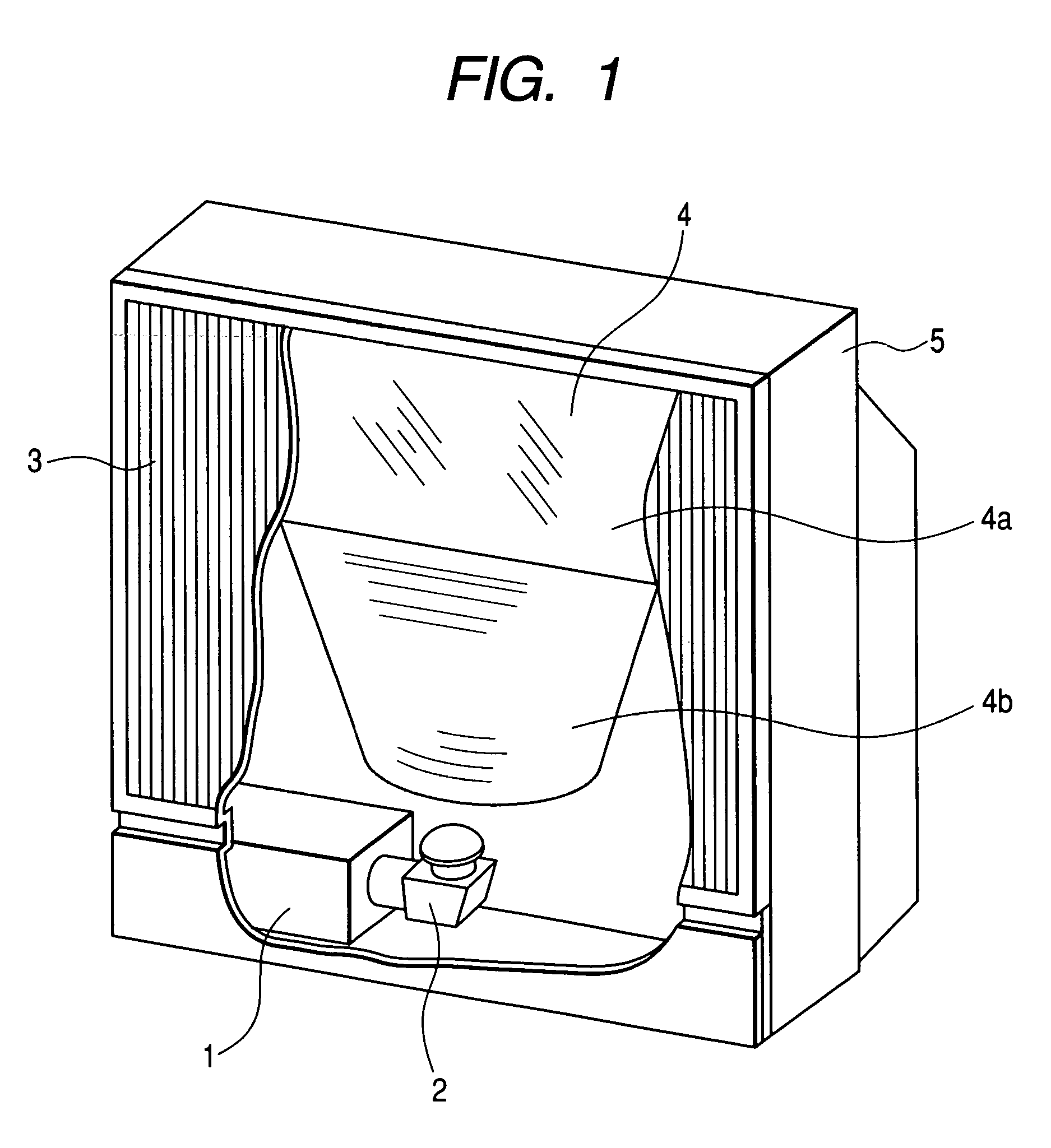
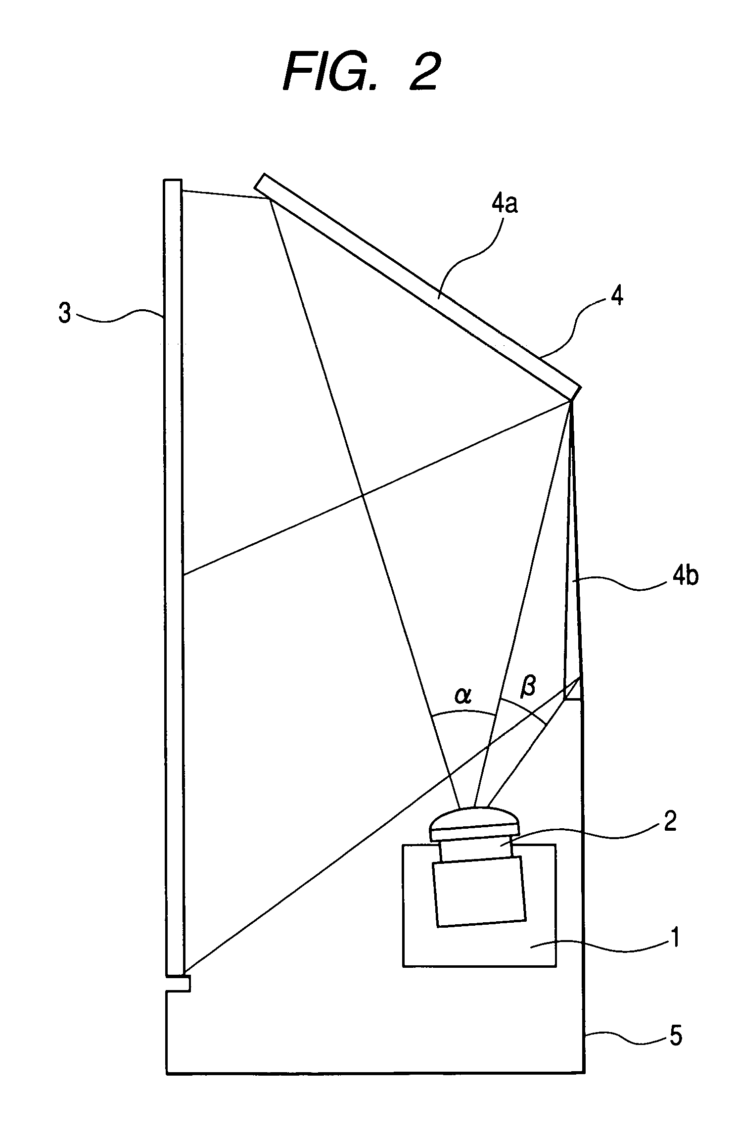
[0023]An embodiment of the present invention will be described hereunder with reference to the accompanying drawings. FIG. 1 is a partially sectional perspective view of an image display apparatus according to the present invention. An image generation source 1 is constructed of a projection-type cathode-ray tube or a reflective / transmissive liquid-crystal panel, an image modulation element such as a display element having a plurality of very small mirrors, and other elements. The image generation source 1 displays a compact image on its display surface according to a particular signal level of an input video signal. A projection lens 2 projects the image displayed by the image generation source 1, onto a transmissive screen 3. Since the projection lens 2 is usually long in projection distance, a reflecting mirror 4 is provided halfway on an optical path between the projection lens 2 and the transmissive screen in order to reduce a depth of the set. The projected image from the proj...


PUM

PropertyMeasurementUnit
heightaaaaaaaaaa
heightaaaaaaaaaa
length L2aaaaaaaaaa

Abstract

The present invention provides a technique suitable for making a set more compact by realizing reduction in height and reduction in depth. An image display apparatus of the present invention includes a reflecting mirror (4) for reflecting the image sent from a projection lens (2), and guiding the image to a transmissive screen (3). The reflecting-mirror (4) includes a planar mirror section (4a) for reflecting, of the entire image exiting the projection lens (2), only image portions projected onto the upper section of the transmissive screen (3), and a Fresnel mirror section (4b) with multiple reflective prisms for reflecting only image portions projected onto the lower section of the screen (3).

Description

CLAIM OF PRIORITY[0001]The present application claims priority from Japanese Application serial no. JP 2004-315002 field on Oct. 29, 2004, the content of which is hereby incorporated by reference into this application.BACKGROUND OF THE INVENTION[0002](1) Field of the Invention[0003]The present invention relates to a technique for making more compact an image display apparatus that displays incoming images formed by an image generation source in enlarged and projected form on a transmissive screen.[0004](2) Description of the Related Art[0005]A projection-type image display apparatus (hereinafter, the apparatus may also be called “set”) enlarges, via a projection lens or the like, the image displayed on the element operating as a small-size image generation source such as projection-type cathode-ray tube or liquid-crystal display element, and forms this image on a transmissive screen by projecting the image thereonto.[0006]Such an image display apparatus is required to be thinned dow...

Claims


Application Information

Patent Timeline
Patent Type & Authority Patents(United States)
IPC IPC(8): G03B21/56G02B3/08G03B21/60G02F1/13G02F1/1335G03B21/10G03B21/28G03B21/62H04N5/74
CPCG03B21/10G03B21/28H04N5/74H04N9/3141
Inventor IMAFUKU, DAISUKEYOSHIKAWA, HIROKIOHISHI, TETSU
Owner MAXELL HLDG LTD
Why Eureka
Try Eureka