Stage apparatus and camera shake correction apparatus using the stage apparatus

a technology of camera shake and stage apparatus, which is applied in the field of stage apparatus and camera shake correction apparatus using the stage apparatus, can solve the problems of considerable thickness, and achieve the effect of reducing the difference between the amount of camera shak

Inactive Publication Date: 2008-12-02
RICOH IMAGING COMPANY
View PDF17 Cites 12 Cited by
  • Summary
  • Abstract
  • Description
  • Claims
  • Application Information

AI Technical Summary

Benefits of technology

[0028]In an embodiment, a camera shake correction apparatus is provided, having a stage apparatus including a stationary support member; a movable stage plate supported by the stationary support member to be movable in a plane relative to the stationary support member; an X-axis direction magnetic force generator and a Y-axis direction magnetic force generator which are provided integral with the stationary support member; an X-axis direction drive coil for generating a driving force in a specific X-axis direction in the plane and receives a magnetic force generated by the X-axis direction magnetic force generator to produce a driving force for driving the movable stage plate in the X-axis direction in the plane; a Y-axis direction drive coil for generating a driving force in a Y-axis direction, which is perpendicular to the X-axis direction, in the plane and receives a magnetic force generated by the Y-axis direction magnetic force generator to produce a driving force for driving the movable stage plate in the Y-axis direction in the plane; an X-direction-coil hole in which the X-axis direction drive coil is fixedly fitted; a Y-direction-coil hole in which the Y-axis direction drive coil is fixedly fitted; an X-direction-sensor hole formed on the movable stage plate having an X-axis direction position sensor fixedly fitted therein for detecting a position of the movable stage plate in the X-axis direction in the plane; a Y-direction-sensor hole formed on the movable stage plate having a Y-axis direction position sensor fixedly fitted therein for detecting a position of the movable stage plate in and Y-axis direction in the plane. The camera shake correction apparatus include a camera which incorporates the stage apparatus; an image pickup device positioned behind a photographing optical system of the camera, having an imaging surface located on an image plane of the photographing optical system, the image pick device being movable together with the movable stage plate; a camera shake detection sensor which detects camera shake of the camera; and a controller which applies a voltage to at least one of the X-axis direction drive coil and the Y-axis direction drive coil to reduce a difference between the amount of the camera shake detected by the camera shake detection sensor and the amount of movement of the movable stage plate which is detected using the X-axis direction position sensor and the Y-axis direction position sensor.
[0029]In an embodiment, a camera shake correction apparatus is provided, having a stage apparatus including a stationary support member; a movable stage plate supported by the stationary support member to be movable in a plane relative to the stationary support member; an X-axis direction magnetic force generator and a Y-axis direction magnetic force generator which are provided integral with the stationary support member; an X-axis direction drive coil for generating a driving force in a specific X-axis direction in the plane and receives a magnetic force generated by the X-axis direction magnetic force generator to produce a driving force for driving the movable stage plate in the X-axis direction in the plane; a Y-axis direction drive coil for generating a driving force in a Y-axis direction, which is perpendicular to the X-axis direction, in the plane and receives a magnetic force generated by the Y-axis direction magnetic force generator to produce a driving force for driving the movable stage plate in the Y-axis direction in the plane; an X-direction-coil hole in which the X-axis direction drive coil is fixedly fitted; a Y-direction-coil hole in which the Y-axis direction drive coil is fixedly fitted; an X-direction-sensor hole formed on the movable stage plate having an X-axis direction position sensor fixedly fitted therein for detecting a position of the movable stage plate in the X-axis direction in the plane; a Y-direction-sensor hole formed on the movable stage plate having a Y-axis direction position sensor fixedly fitted therein for detecting a position of the movable stage plate in and Y-axis direction in the plane. The camera shake correction apparatus includes a camera which incorporates the stage apparatus; a correction lens located in front of an image plane of a photographing optical system of the camera, positioned so that an optical axis of the correction lens coincides with an optical axis of the photographing optical system, and being movable together with the movable stage plate; a camera shake detection sensor which detects camera shake of the camera; and a controller which applies a voltage to at least one of the X-axis direction drive coil and the Y-axis direction drive coil to reduce a difference between the amount of the camera shake detected by the camera shake detection sensor and the amount of movement of the movable stage plate which is detected using the X-axis direction position sensor and the Y-axis direction position sensor.
[0030]According to the present invention, the thickness of a portion of the stage apparatus in the optical axis direction at which the coil overlies the movable stage plate becomes smaller than that of a conventional stage apparatus because the coil is fixedly fitted into the recess formed on the movable stage plate. Accordingly, the stage apparatus and the camera shake correction apparatus using the stage apparatus can be miniaturized in the forward / rearward direction. Moreover, even if the magnetic force generator is miniaturized and make thinner, the movable stage plate can be made to operate in the same manner as in the prior art since it is easier for the magnetic force generated by the magnetic force generator to act on the coil than before.

Problems solved by technology

However, due to advancements in the reduction in thickness of cameras in recent years, such a total thickness has become a considerable problem.

Method used


Image

  • Stage apparatus and camera shake correction apparatus using the stage apparatus
  • Stage apparatus and camera shake correction apparatus using the stage apparatus
  • Stage apparatus and camera shake correction apparatus using the stage apparatus

Examples


Embodiment Construction

[0048]An embodiment of a camera shake correction apparatus (image stabilizer) according to the present invention will be hereinafter discussed with reference to the attached drawings.

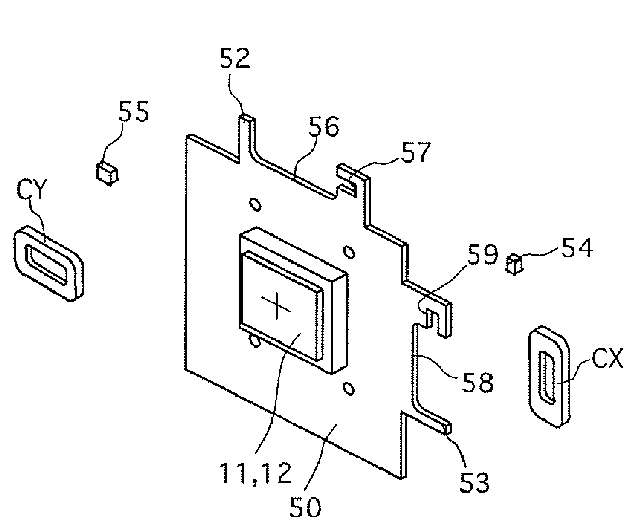
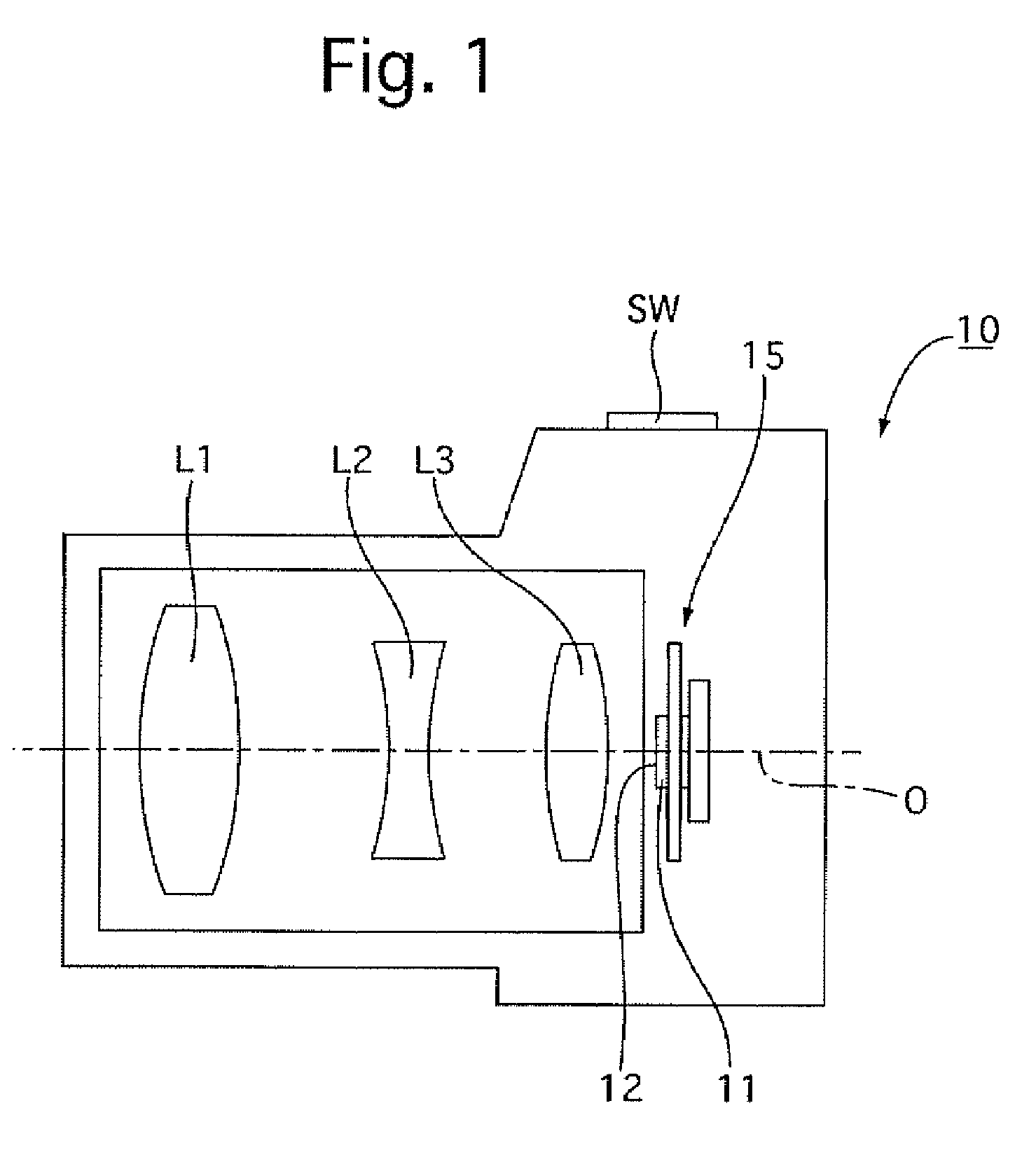
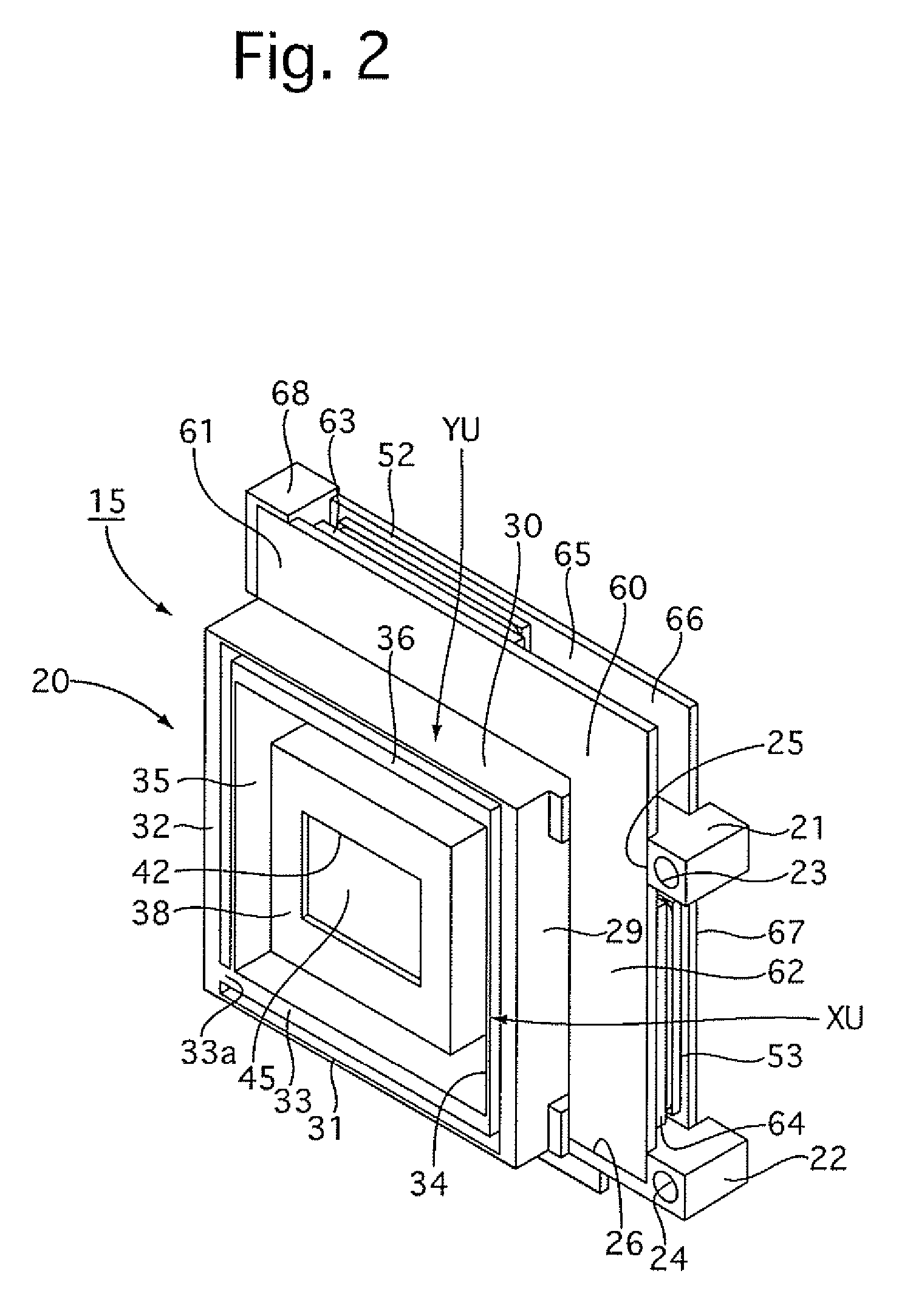
[0049]The camera shake correction apparatus 15 is incorporated in a digital camera 10 (in a camera body thereof) as shown in FIG. 1. As shown in FIG. 1, the digital camera 10 is provided therein with a photographing optical system including a plurality of lenses L1, L2 and L3. An image pickup device (e.g., CCD or CMOS image sensor) 11 is provided behind the lens L3. The image pickup device 11 is provided with an imaging surface (image-forming plane) 12 which is located on an image plane of the photographing optical system and is perpendicular to an optical axis O of the photographing optical system. The image pickup device 11 is secured to the camera shake correction apparatus (stage apparatus) 15 that is incorporated in the digital camera 10.

[0050]The camera shake correction apparatus 15 that is fixed ...


PUM


Abstract

A stage apparatus includes a stationary support member, a movable stage plate supported by the stationary support member to be movable in a plane relative to the stationary support member, at least one magnetic force generator which is provided integral with the stationary support member, and at least one coil which is mounted on the movable stage plate and receives a magnetic force generated by the magnetic force generator to produce a driving force for driving the movable stage plate in the plane. At least one hole in which the coil is fixedly fitted is formed on the movable stage plate.

Description

BACKGROUND OF THE INVENTION[0001]1. Field of the Invention[0002]The present invention relates to a stage apparatus for substantially linearly moving a structural component, that supports an element, e.g., an image pickup device or the like, in two orthogonal directions in a plane, and a camera shake correction apparatus using such a stage apparatus.[0003]2. Description of the Prior Art[0004]A known stage apparatus used as a camera shake correction apparatus in which a movable stage plate is substantially linearly moved in two orthogonal directions in a plane is described in, for example, Japanese laid-open patent publication No. 2001-215543.[0005]Such a known stage apparatus (shake correction apparatus) provided in a digital camera is provided with a stationary support member, a movable stage plate, an image pickup device, a magnetic force generator, an X-axis direction drive coil and a Y-axis direction drive coil. The stationary support member is fixed to a camera body. The movable...

Claims


Application Information

Patent Timeline
Patent Type & Authority Patents(United States)
IPC IPC(8): G03B17/00
CPCG03B5/00H04N5/2253H04N5/23248H04N5/23258H04N5/23287G03B2205/0015G03B2205/0069G03B2205/0038H04N23/54H04N23/68H04N23/6812H04N23/687
Inventor HIRUNUMA, KENENOMOTO, SHIGEO
Owner RICOH IMAGING COMPANY
Why Eureka
Try Eureka