Thermostat display system providing adjustable backlight and indicators

a display system and thermostat technology, applied in the field of digital thermostats, can solve the problems of not providing any indication of the active status of heating or cooling equipment in the home, the overall user experience of interfacing with such a digital thermostat has not kept pace, and several consumer complaints

Inactive Publication Date: 2008-12-02
RANCO OF DELAWARE
View PDF36 Cites 79 Cited by
  • Summary
  • Abstract
  • Description
  • Claims
  • Application Information

AI Technical Summary

Benefits of technology

[0012]In one embodiment of the present invention for which the display system of the present invention finds particular applicability, a digital thermostat includes at least one indicator light. Typically, this indicator light is an LED indicator that may be used for various functions, including display of the operational status of the heating and / or air conditioning system equipment. The display system of the present invention allows the user the ability to adjust the illumination intensity provided by the indicator. In a preferred embodiment, the system of the present invention allows a user to adjust the display intensity from full on to full off as desired by the user.
[0013]In another embodiment of the present invention, wherein the thermostat includes a backlit user display screen, the system of the present invention also provides the ability for a user to adjust the intensity of the backlight illumination. Preferably, the system of the present invention allows the user to adjust the backlight illumination intensity from full on to full off.
[0014]In an embodiment of the present invention wherein the thermostat includes both LED indicators and a backlit user display screen, the system of the present invention preferably provides the ability to adjust the display intensities of both the backlit user display screen and the LED indicators. In such a system, the user is able to control the intensity of each of these elements from full on to full off as desired by the user.
[0016]In one embodiment of the present invention, the illumination intensity of the LED indicators and / or backlight of the user display screen is controlled via a pulse with modulated (PWM) controlled output that drives the indicators and / or backlight. The software of the thermostat, preferably via the menu driven user interface, can adjust the intensity of the indicators and / or backlight from full intensity (via 100% duty cycle or high current pulses without going completely on) to completely off. In addition, the PWM control allows the user to set many other intensity levels, e.g., 25%, 50%, 75%, etc. as desired. These other intensity levels may not be as annoying to the user while still allowing the indicators and / or backlit user display to perform the function for which they were originally intended.

Problems solved by technology

While the advances that are being included in modern digital thermostats greatly enhance the users' comfort level and minimize the energy usage, the overall user experience interfacing with such a digital thermostat has not kept pace.
Specifically, while such digital thermostats typically provide some form of user interface screen from which information is conveyed to the consumer, and from which the consumer may program the operation of the thermostat, such displays do not provide any indication that the heating or cooling equipment in the home is active.
However, such LED indicators have led to several consumer complaints, and in some cases, reduction in performance of the thermostat itself.
Unfortunately, many consumers have complained that such an LED indication is annoying, distracting, and unwanted in several situations.
Another is when the thermostat is installed in a bedroom or other area where such a bright LED indicator would prove to be annoying.
The user is then forced to repeatedly remove the tape to determine the operational status, and replacing the tape when such LED indication would prove annoying or distracting.
However, such modification of the electronics may lead to spurious operation of the thermostat, damage to the thermostat, risk to the consumer, etc.
Another source of annoyance is from the intensity of the illumination of the backlit user display.
However, when the thermostat is accessed during the night or when it is quite dark in the room in which the thermostat is installed, the intensity of the backlight illumination is overwhelming, particularly to consumers whose eyes have adjusted to the dark.

Method used


Image

  • Thermostat display system providing adjustable backlight and indicators
  • Thermostat display system providing adjustable backlight and indicators
  • Thermostat display system providing adjustable backlight and indicators

Examples


Embodiment Construction

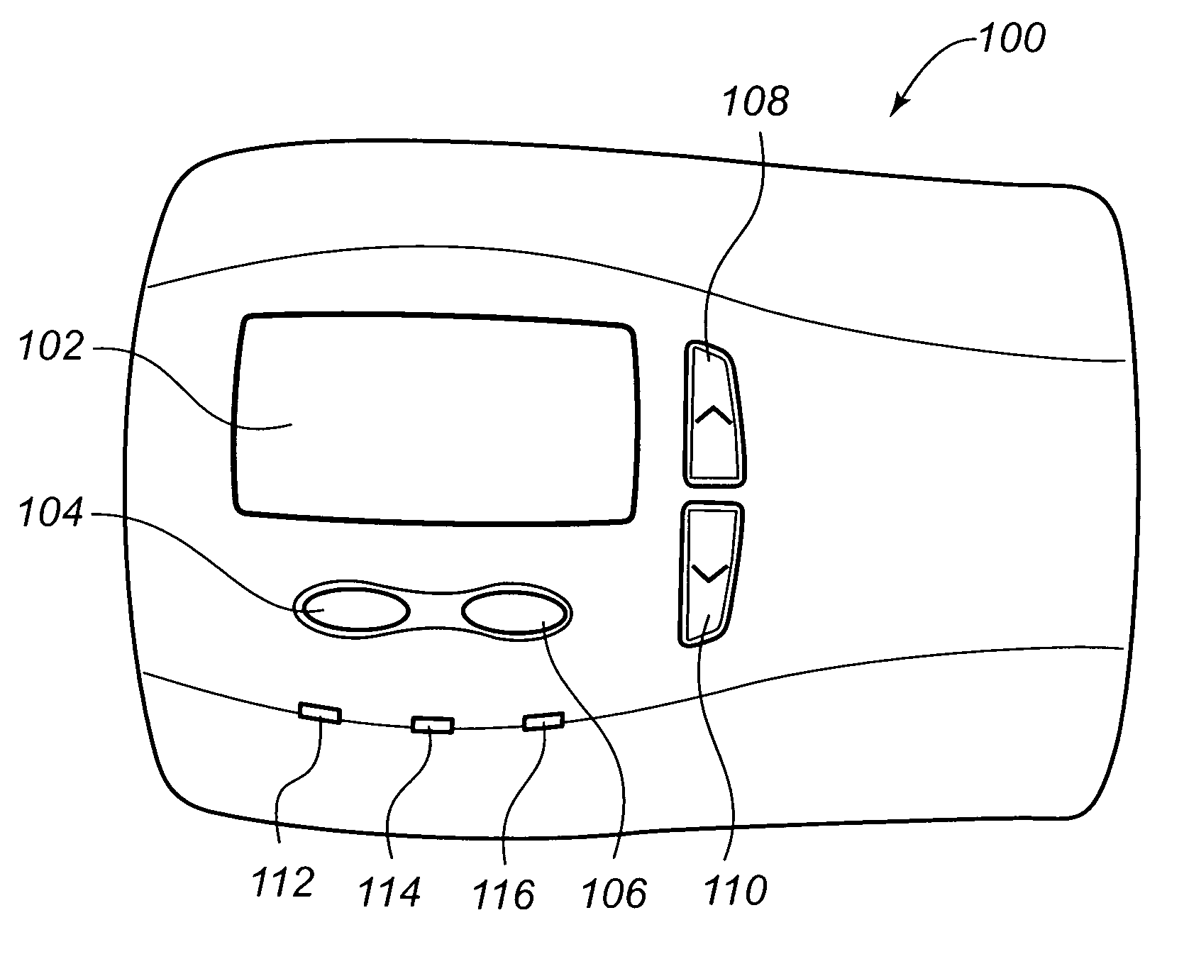
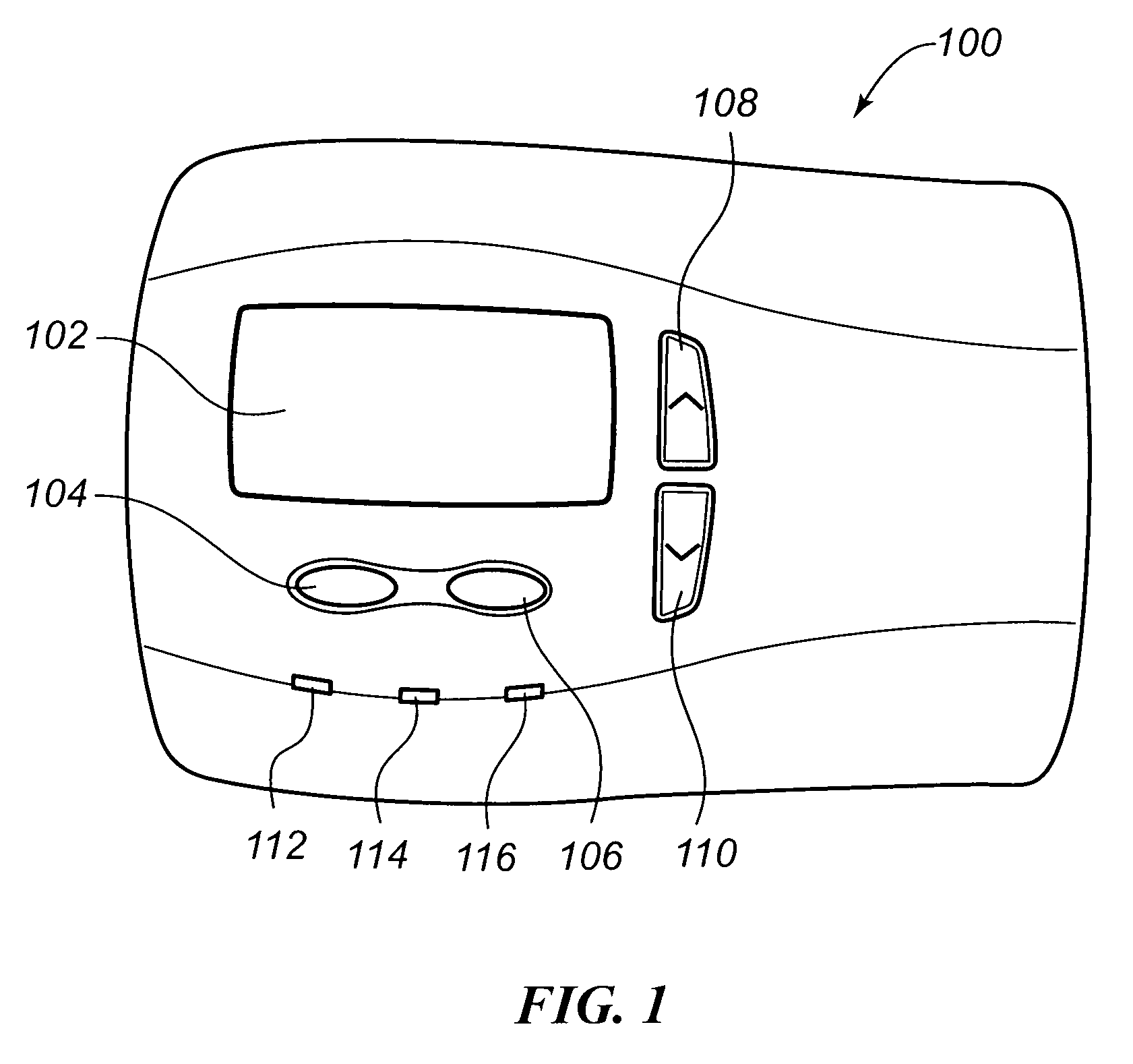
[0023]An embodiment of a thermostat constructed in accordance with the teachings of the present invention that incorporates the display system of the present invention is illustrated in FIG. 1. As with many thermostats, an internal temperature sensor that is monitored by the internal processor is included within the thermostat 100. As may be seen from this FIG. 1, this embodiment of the thermostat 100 includes a user display 102 on which is displayed programmatic, system, and ambient information regarding the operation of the HVAC system. This user display 102 may take various forms as are well known in the art, and in a preferred embodiment is a dot matrix LCD display. The user display screen 102 may be selectively illuminated by backlight illumination, and therefore may be referred to as a backlit user display screen 102. The control of the intensity of this illumination in accordance with the system of the present invention will be discussed more fully below.

[0024]With such a dis...


PUM


Abstract

A user adjustable visual display system and method for a digital thermostat having a backlit user display screen and system operation indicators is provided. The system allows a user to programmatically vary the illumination intensity of the backlit user display screen and the operational indicators. The variance provided includes disabling of the backlight and operational indicators. The system utilizes a variable pulse width modulated (PWM) intensity control for the backlight and indicators. Alternatively, an adjustable current drive illumination control is used to control the backlight and indicators. The selection of the desired intensity is provided via a display settings menu accessed via the user display screen.

Description

FIELD OF THE INVENTION[0001]The present invention relates generally to digital thermostats, and more particularly to a display system for a digital thermostat to convey system operating information to a user.BACKGROUND OF THE INVENTION[0002]Occupants of dwellings and commercial structures have long benefited from the inclusion of a heating, ventilating, and air conditioning (HVAC) system that regulates the temperature and humidity within the dwelling or structure. Traditionally, the thermostat that controlled this temperature regulating equipment was a fairly simple electromechanical device that was simply wired to a heating device and / or to a cooling device. Once installed, the user need only move a selector switch between heating and cooling to designate which equipment was desired to be operated, move a selector switch between run and auto for a fan control, and rotate a dial to a desired set point temperature. No other user interface to the thermostat was needed or available, an...

Claims


Application Information

Patent Timeline
Patent Type & Authority Patents(United States)
IPC IPC(8): G05D23/00G09G3/36
CPCG05D23/1902G05B2219/2642G09G3/3406G09G2320/0606G09G2320/0626G05D23/19
Inventor CHAPMAN, JR., JOHN GILMANCATLIN, GEORGE NHOCKENSMITH, BRIAN
Owner RANCO OF DELAWARE
Why Eureka
Try Eureka