Fire control system of elevator

a control system and elevator technology, applied in the direction of elevators, building lifts, transportation and packaging, etc., can solve the problems of insufficient use of individual identification information of elevator users, difficulty in high-accuracy grasping of the number of rests on each floor,

Inactive Publication Date: 2008-12-09
MITSUBISHI ELECTRIC CORP
View PDF14 Cites 39 Cited by
  • Summary
  • Abstract
  • Description
  • Claims
  • Application Information

AI Technical Summary

Problems solved by technology

However, in conventional fire control systems of an elevator, the individual identification information of elevator users is not utilized.
Therefore, it is difficult to perform high-accuracy grasping of the number of remainders on each floor, and appropriate evacuating operations based on the grasping of the accurate number of remainders, priority evacuating operations based on the grasping of the characteristics of remainders (the weak), supply of evacuation guidance signs to individual remainders and the like are not performed.

Method used


Image

  • Fire control system of elevator
  • Fire control system of elevator
  • Fire control system of elevator

Examples


embodiment 1

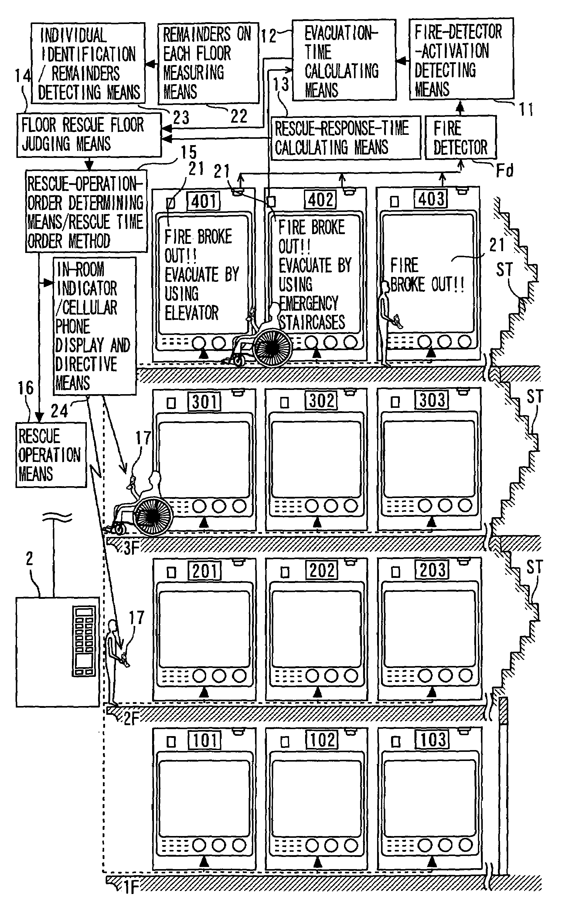
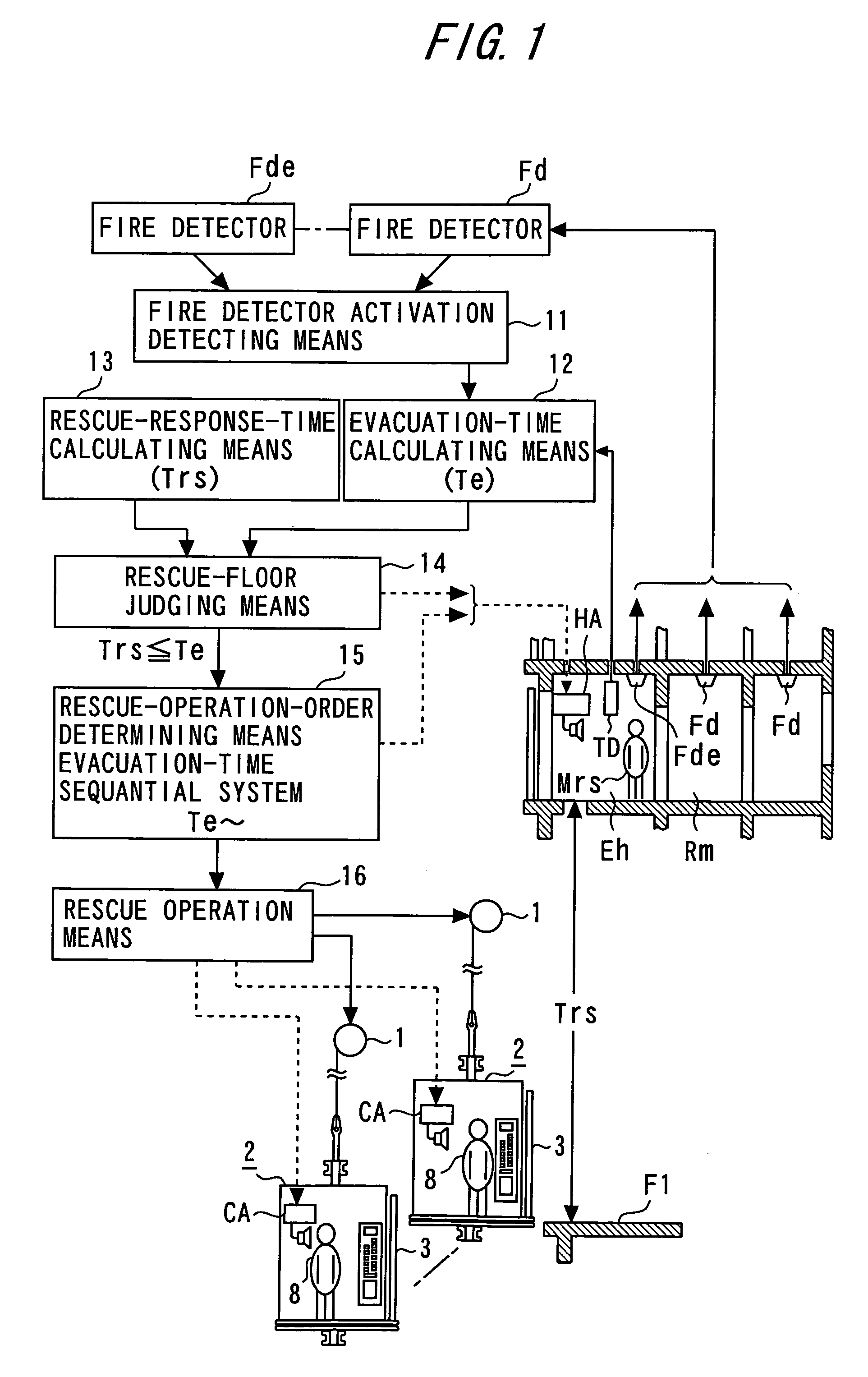
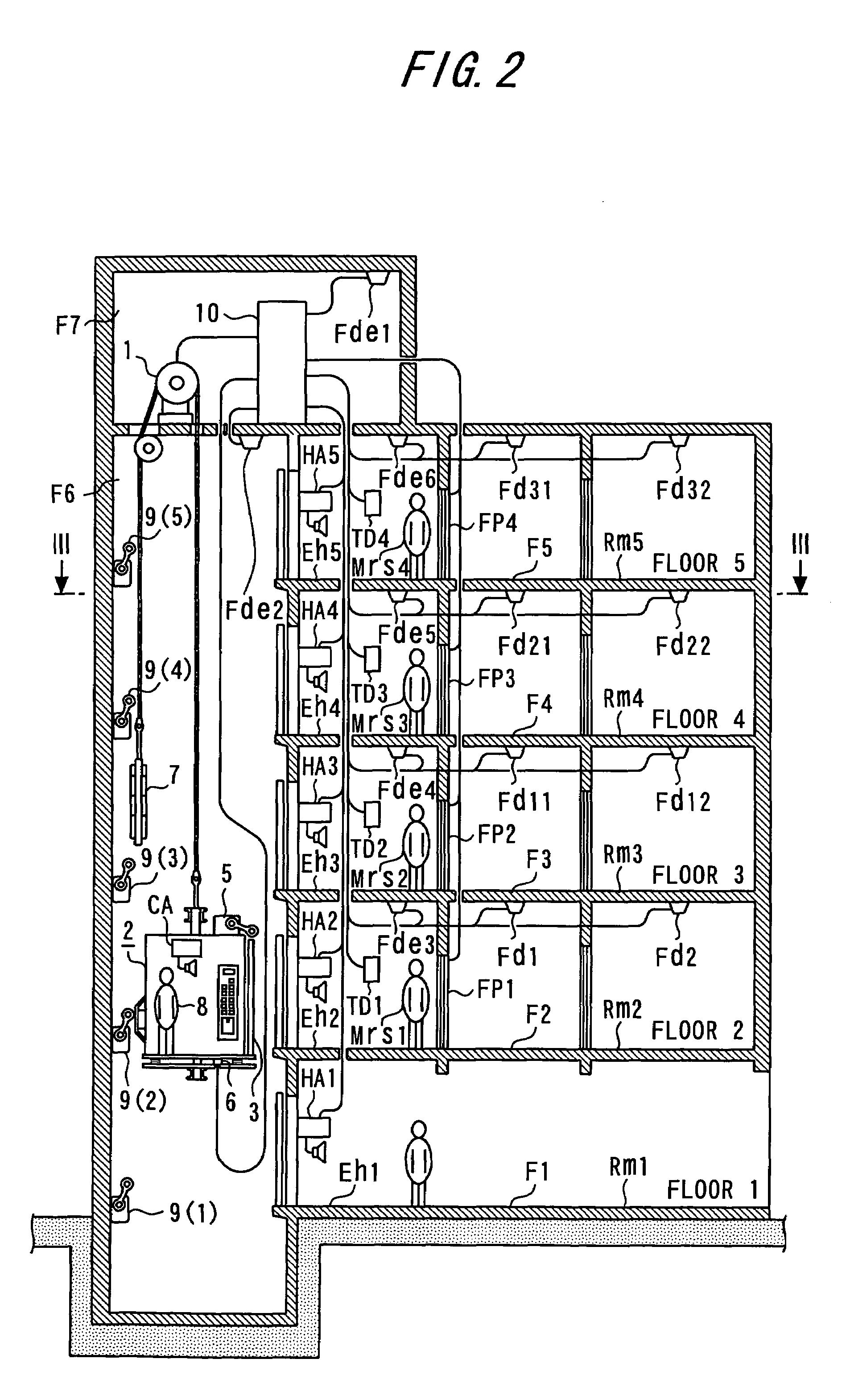
[0112]FIGS. 20 and 21 each show a partial construction of a fire control system of an elevator related to Embodiment 1 of the present invention, which is obtained by adding improvements to the fire control system of an elevator on which the present invention is based, which fire control system is shown in FIGS. 1 to 19. FIG. 20 is a block diagram which shows how individual identification information sent from terminals carried by individuals during an elevator use is received and utilized, and FIG. 21 is a block diagram which shows how rescue operations during a fire, evacuation guidance signs to individual remainders and the like are notified. In Embodiment 1 of the present invention, the invention will be described by taking a case where the present invention is applied to a four-storied apartment building as an example. However, the present invention is not limited to this and can also be applied to an office building and a multi-tenant building.

[0113]This apartment building is a...

embodiment 2

[0114]In Embodiment 1, descriptions were given of a system in which a key provided with a noncontact tag, a card provided with a noncontact tag, a cellular phone provided with a noncontact tag, etc. are used as the individual identification sending means 17. However, the present invention can also be easily carried out in a system in which a fingerprint matching device and a card reader are used as the individual identification means.

embodiment 3

[0115]In Embodiment 1, a case in which the in-room indicator 21 is installed in each residential room was described. However, the present invention can also be easily carried out in a case where a dedicated server is installed in a telephone company and telephone calls are given to a cellular phone of each individual in liaison with an elevator system.


PUM


Abstract

Provided is a fire control system of an elevator which rescues remainders in a building to a rescue floor by causing an elevator car to perform evacuating operations when a fire detector installed in the building works, characterized in that the fire control system of an elevator includes: individual identification sending means which each individual who utilizes the elevator carries and in which a resident room number, a resident floor, information on characteristics of each individual, etc. are registered; individual identification receiving means provided in each elevator hall; and a controller which calls an elevator car and performs car-call registration of a destination floor on the basis of information sent from the individual identification sending means to the individual identification receiving means. The controller includes remainders -on-each-floor measuring means which calculates the number of remainders on each floor from car-call registration information of the destination floor, remainders -on-each-floor detecting means which detects the calculated number of remainders on each floor, evacuation guiding and direction giving means which performs evacuation guidance and giving directions during a fire on the basis of the detected number of remainders on each floor, and rescue operation means which performs rescue operations.

Description

TECHNICAL FIELD[0001]The present invention relates to a fire control system of an elevator which performs high-accuracy grasping of the number of remainders on each floor and of the characteristics of the remainders when a fire breaks out in a building, thereby to select an optimum evacuating operation and to be able to perform an appropriate rescue guidance for the remainders.BACKGROUND ART[0002]Fire control systems of an elevator which rescue persons remaining in a building when a fire breaks out have hitherto been known. For example, the U.S. Pat. No. 6,000,505 discloses a multistory building having an elevator system capable of being used to transfer building occupants between floors during a fire. This elevator system can work during a fire as emergency escape and evacuation means that includes a control unit which controls the movement of elevator cars between selected floors within an emergency evacuation zone and evacuates building occupants to a designated evacuation suppor...

Claims


Application Information

Patent Timeline
Patent Type & Authority Patents(United States)
IPC IPC(8): B66B1/20B66B5/02
CPCB66B5/021B66B5/024
Inventor KAWAI, KIYOJI
Owner MITSUBISHI ELECTRIC CORP
Why Eureka
Try Eureka