Display device lighting unit

a technology for display devices and lighting units, which is applied in lighting and heating apparatus, lighting support devices, instruments, etc., can solve the problems of increasing electrical consumption, increasing total heat generation, and affecting display quality or reliability, and achieves the effects of reducing the number of LEDs

Active Publication Date: 2008-12-09
SHARP KK
View PDF50 Cites 8 Cited by
  • Summary
  • Abstract
  • Description
  • Claims
  • Application Information

AI Technical Summary

Benefits of technology

[0097]As the means for reducing the lamp supporting area in the above-mentioned form (3), there may be mentioned, for example, the embodiment in which each supporting member is provided with projections so that the area of contacting of a light source lamp with the relevant supporting member of the lamp holder may be reduced. In addition to such embodiment, any form capable of reducing the area of contacting between a light source lamp and the relevant supporting member of the lamp holder can produce the effects of the invention. As a result, the temperature distribution in each light source lamp can be made uniform and, therefore, it becomes possible to improve the uniformity in brightness of the lighting unit. The supporting members of the lamp holder are preferably made of a material low in thermal conductivity.
[0098]In the above-mentioned form (4), the lamp holder judiciously comprises supporting members and fixing members with at least one of the fixing members having a structure resulting from division into two. With a lamp holder having such a constitution, a light source lamp can be fixed within the relevant supporting member of the lamp holder through the corresponding fixing member by opening and closing the fixing member before fixation to the backlight angle or reflector and, after fixation of the fixing member with the light source lamp held in the supporting member, the fixation member cannot be opened or closed any longer. As a result, the light source lamp can be maintained at a sufficient level of holding strength.
[0099]As the manner of fixation of a lamp holder after light source lamp fixation on a supporting member or members of the lamp holder to a backlight angle (e.g. sheet metal) in the display device lighting unit, there may be mentioned, for example, the embodiment in which the lower part (fixing member) of the lamp holder has a shape capable of opening and closing in the downward direction (in the direction toward the backlight angle) and, after light source lamp fixation in the relevant supporting member of the lamp holder through the lower part (fixing member), the lower part (fixing member) of the lamp holder is inserted into the backlight angle. In this case, the lower part (fixing member) of the lamp holder is preferably made of a material having a certain degree of freedom, for example a Si (silicone) rubber since the procedure for opening the lower part (fixing member) in the downward direction for light source lamp fixation and the procedure for insertion into the backlight angle become easy.
[0100]Such modes and forms bring about improvements with respect to deviations in lamp mounting. Now, referring to the drawings, the mounting of a light source lamp(s) in the step of assemblage is described in detail.
[0101]FIG. 3A and FIG. 3B each shows an example of the U-shaped curved portion supporting form for a light source lamp having a curved portion. When a lamp holder formed of a Si rubber or the like is given a notch and a lamp is to be inserted therein, as shown in FIG. 3A, the mounting in the step of assemblage is difficult to perform. When the lower part (fixing member) of a lamp holder is fixed to a backlight angle in a display device lighting unit and then a light source lamp is fixed on the supporting member of the lamp holder, as shown in FIG. 3B, namely when the lower part (fixing member) of the lamp holder is inserted into the backlight angle and then the supporting member of the lamp holder is opened in the upward direction (in the direction opposite to the backlight angle) and the light source lamp is fixed in the supporting member, deviations in mounting position in the X direction shown in the figure may possibly be caused. Further, when the supporting member is made of a soft material, for example a Si rubber, deviations in the Y and Z directions may occur, possibly affecting the display quality and reliability of the display device. Referring to FIG. 3E schematically showing the cross section of the lamp holder shown in FIG. 3B, the confining force in the direction of the arrow in the figure is weak when a soft material such as a Si rubber is used and, therefore, deviations in the fixation in the Z direction may result. When such holders are applied to liquid display devices, in particular, there is the possibility of failure to prevent the deviations (shifts) in the directions of the X and Y axes, as shown in FIGS. 3C and 3D, to a satisfactory extent, hence failure to provide a higher and stabilized level of display quality than in the conventional art. In FIGS. 3C and 3D, the positions of U-shaped fluorescent tubes before shifting are indicated by dotted lines, and the positions indicated by solid lines are the positions after shifting in the directions of the arrows.
[0102]When a material lower in elasticity (freedom) than Si rubbers, for example a polycarbonate, is used, it is strong in the Z axis direction but may allow shifting in the X and Y axis directions, as shown in FIGS. 3C and 3D.

Problems solved by technology

Furthermore, the electricity consumption increases, and the total heat generation becomes increased.
However, there is still room for contrivance for adapting these devices to the field of liquid crystal displays, among others, where higher quality and larger sizes are required for improving the commercial value thereof and at the same time reductions in cost are required.
With devices of this kind, however, deviations may result in the step of mounting lamps and such deviations may influence the display quality or reliability.

Method used


Image

  • Display device lighting unit
  • Display device lighting unit
  • Display device lighting unit

Examples


example 1

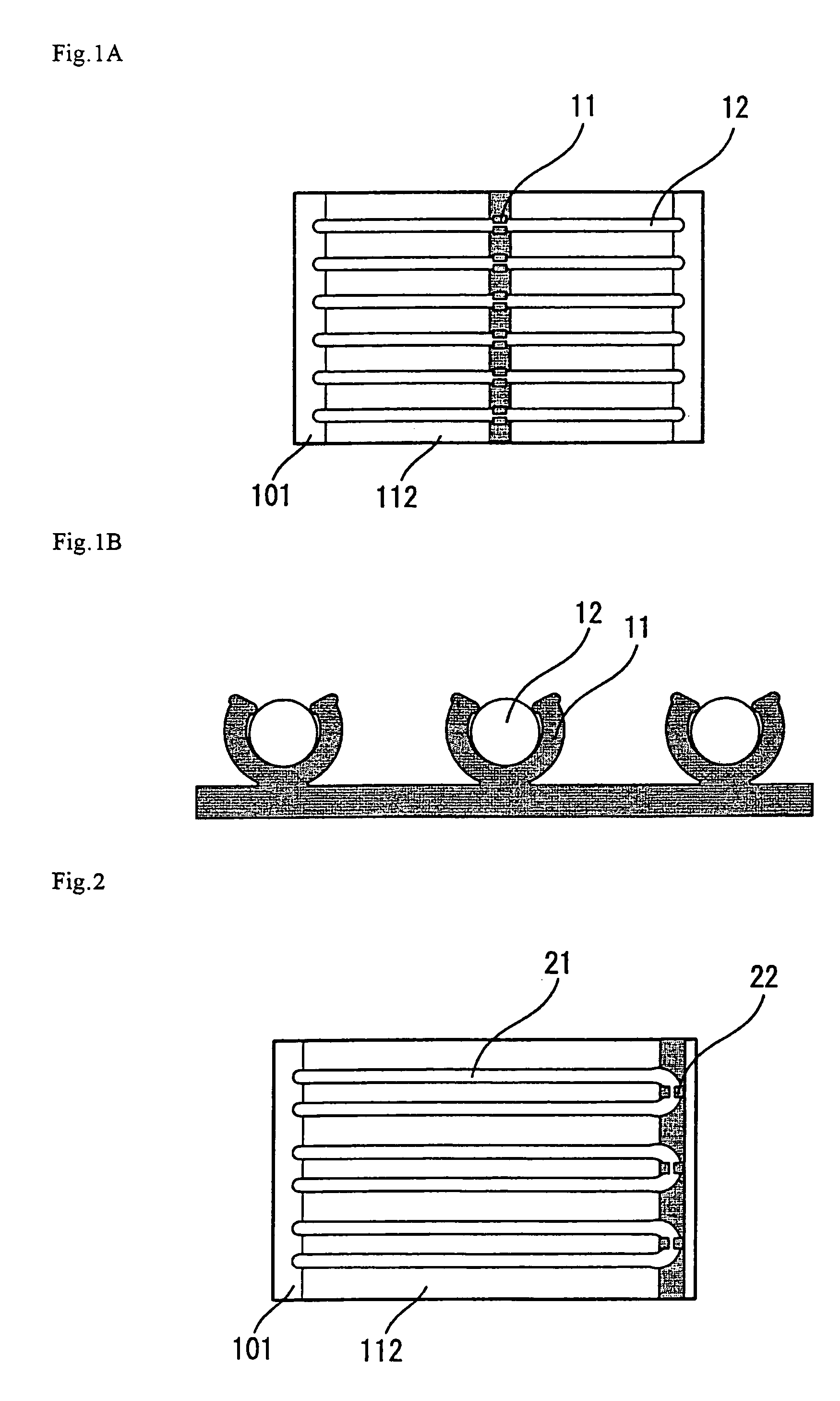
[0133]A lighting unit was constituted by placing, in the display region of a liquid crystal display device having a lighting unit at the back of the liquid crystal display element, a white lamp holder 11 made of an insulating resin and morphologically capable of supporting a plurality of straight tube type fluorescent tubes 12 on a highly reflecting resin 112 and disposing a plurality of straight tube type fluorescent tubes 12 thereon in parallel and at regular intervals, as shown in FIG. 1.

[0134]In this example and the subsequent examples, the shape, material, number and positions of the lamp holders made of an insulating resin are not restricted in any way in the modes of embodiment of the invention. The liquid crystal display device may have either a direct type backlight or an edge light type backlight having a U-shaped lamp or a plurality of U-shaped lamps.

[0135]According to such constitution, lamps are supported by a lamp holder resulting from integration of a plurality of sup...

example 2

[0136]A lighting unit was constituted by disposing, in the non-display region of a liquid crystal display device having a lighting unit at the back of a liquid crystal display element, the supporting members of a lamp holder 22 made of an insulating resin and morphologically capable of supporting a plurality of U-shaped fluorescent tubes (U-shaped tube light source lamps) 21 on a sheet metal 111 and disposing U-shaped fluorescent tubes 21 thereon in parallel and at regular intervals, as shown in FIG. 2.

[0137]According to such constitution, lamps are supported by a lamp holder resulting from integration of a plurality of supporting members into one piece and therefore the number of parts can be reduced and, further, light source lamps can be disposed precisely at regular intervals; thus, liquid crystal display devices excellent in display quality can be provided at low cost.

example 3

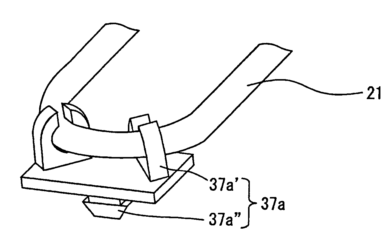
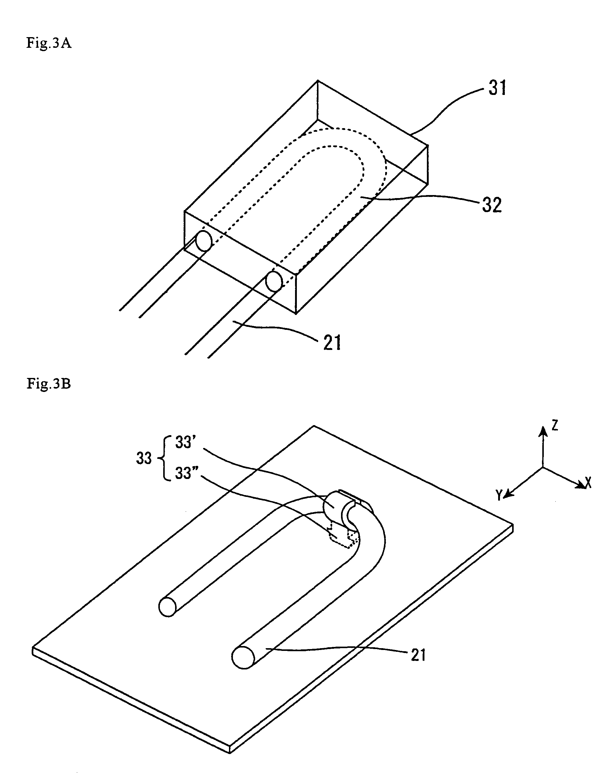
[0138]On the occasion of inserting the U-shaped curved portion of a U-shaped fluorescent tube 21, which is the light source lamp, into a housing frame 41 in the section for housing the fluorescent tube 21 into the housing frame 41 in a liquid crystal display device having a lighting unit at the back of a liquid crystal display element, the U-shaped curved portion of the U-shaped fluorescent tube 21 was supported by a lamp holder 31, 33, 34 or 35 made of an insulating resin and inserted, in that state, into the housing frame 41, as shown in FIG. 3. A lighting unit was thus constituted.

[0139]According to such constitution, that portion of a U-shaped fluorescent tube which is to be housed in a housing frame is housed via a lamp holder made of an insulating resin, so that the U-shaped curved portion of the U-shaped fluorescent tube can be prevented from coming into contact with the housing frame; a good liquid crystal display device can thus be provided.


PUM

PropertyMeasurementUnit
sizeaaaaaaaaaa
sizeaaaaaaaaaa
lengthaaaaaaaaaa

Abstract

The display device lighting unit comprises a light source lamp and a lamp holder, which has one or an arbitrary combination of the following features: (1) the lamp holder comprises a plurality of supporting members at least partly integrated, (2) the light source lamp or lamps have a curved portion and each is supported by supporting members of the lamp holder or holders at least partly at the respective curved portions, (3) the lamp holder has, for example, projections, depressions and so on that reduces the supporting area of the supporting members, (4) means for fixing the lamp holder within the display device lighting unit after the fixation of light source lamp on the supporting members of the lamp holder or holders in which at least one fixing member of the lamp holder or holders have a structure resulting from division into two.

Description

REFERENCE TO RELATED APPLICATIONS[0001]This Nonprovisional application claims priority Under 35 U.S.C. §119(a) on Patent Application No. 2004-6997 filed in Japan on Jan. 14, 2004, No. 2004-223957 filed in Japan on Jul. 30, 2004, and No. 2004-343134 filed in Japan on Nov. 26, 2004, the entire contents of which are hereby incorporated by reference.BACKGROUND OF THE INVENTION[0002]1. Field of the Invention[0003]The present invention relates to a display device lighting unit, a lamp holder and a liquid crystal display device. More particularly, it relates to a display device lighting unit and a lamp holding system therefor, which are suited for use in constituting a backlight for a liquid crystal display device of the transmission or semitransmission type having a transmission region in the liquid crystal display element and to a liquid crystal display device equipped with the display device lighting unit.[0004]2. Prior Art[0005]A display device lighting unit illuminates a device having...

Claims


Application Information

Patent Timeline
Patent Type & Authority Patents(United States)
IPC IPC(8): F21V21/00F21V21/08F21Y103/37G02F1/1335G02F1/13357
CPCG02F1/133604A23L7/10A23P30/00B65G33/265B65G33/18
Inventor ONO, SATOSHITAKEGUCHI, MITSUHIRO
Owner SHARP KK
Why Eureka
Try Eureka