Filling valve

a technology of filling valve and filling chamber, which is applied in the direction of filling without pressure, liquid handling, packaging goods, etc., can solve the problems of time-consuming operation, inapplicability of technique, and fungus beds

Active Publication Date: 2008-12-16
SHIBUYA IND CO LTD
View PDF14 Cites 9 Cited by
  • Summary
  • Abstract
  • Description
  • Claims
  • Application Information

AI Technical Summary

Benefits of technology

[0006]Accordingly, it is an object of the present invention to provide a filling valve which permits a combined use in a filling of a carbonated beverage and a filling of a non-carbonated beverage and which can accommodate for a filling operation in a clean environment.
[0008]In accordance with the invention, a gas exhaust passage is not provided within the valve housing, and when a carbonated filling operation is to be performed, the first liquid outlet member which is connected to the gas exhaust passage is mounted. Alternatively, for a non-carbonated filling operation, the second liquid outlet member having a screen attached to its lower end is mounted. In this manner, there is obtained a filling valve which permits a combined use with a carbonated beverage and a non-carbonated beverage and which can accommodate for a clean environment.

Problems solved by technology

With this arrangement, there arises a risk that fungus beds may form in clearances formed between pins which are disposed as a press fit and internal surfaces of bores formed in the valve housing, and therefore, this technique is inapplicable when the filling operation should take place in a clean environment.
However, it is a time taking operation to attach screens to a number of nozzles.
This is undesirable in an arrangement which performs a filling operation in a clean environment where the number of locations which must be cleansed should be reduced as much as possible.

Method used


Image

  • Filling valve
  • Filling valve
  • Filling valve

Examples


Embodiment Construction

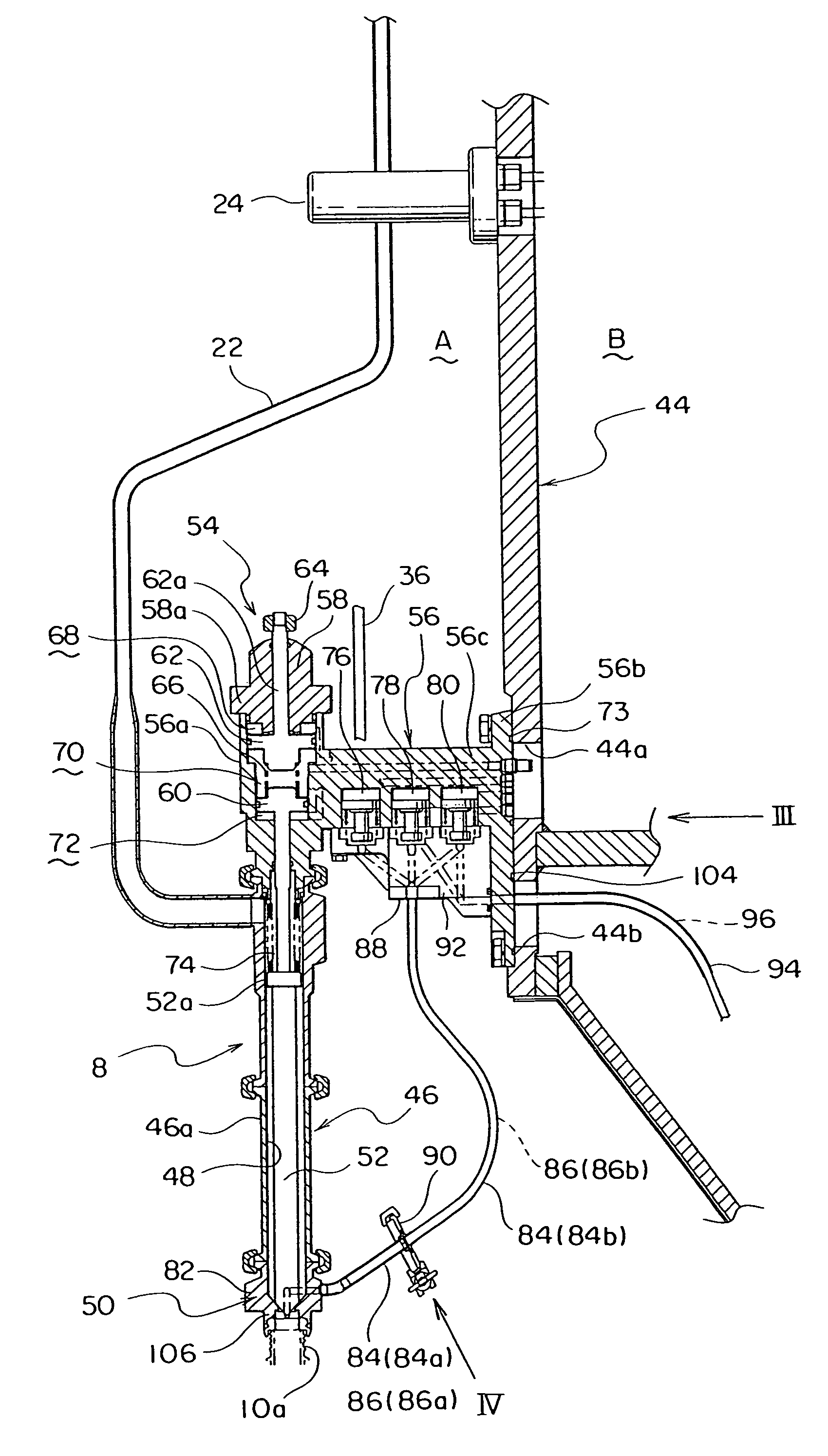
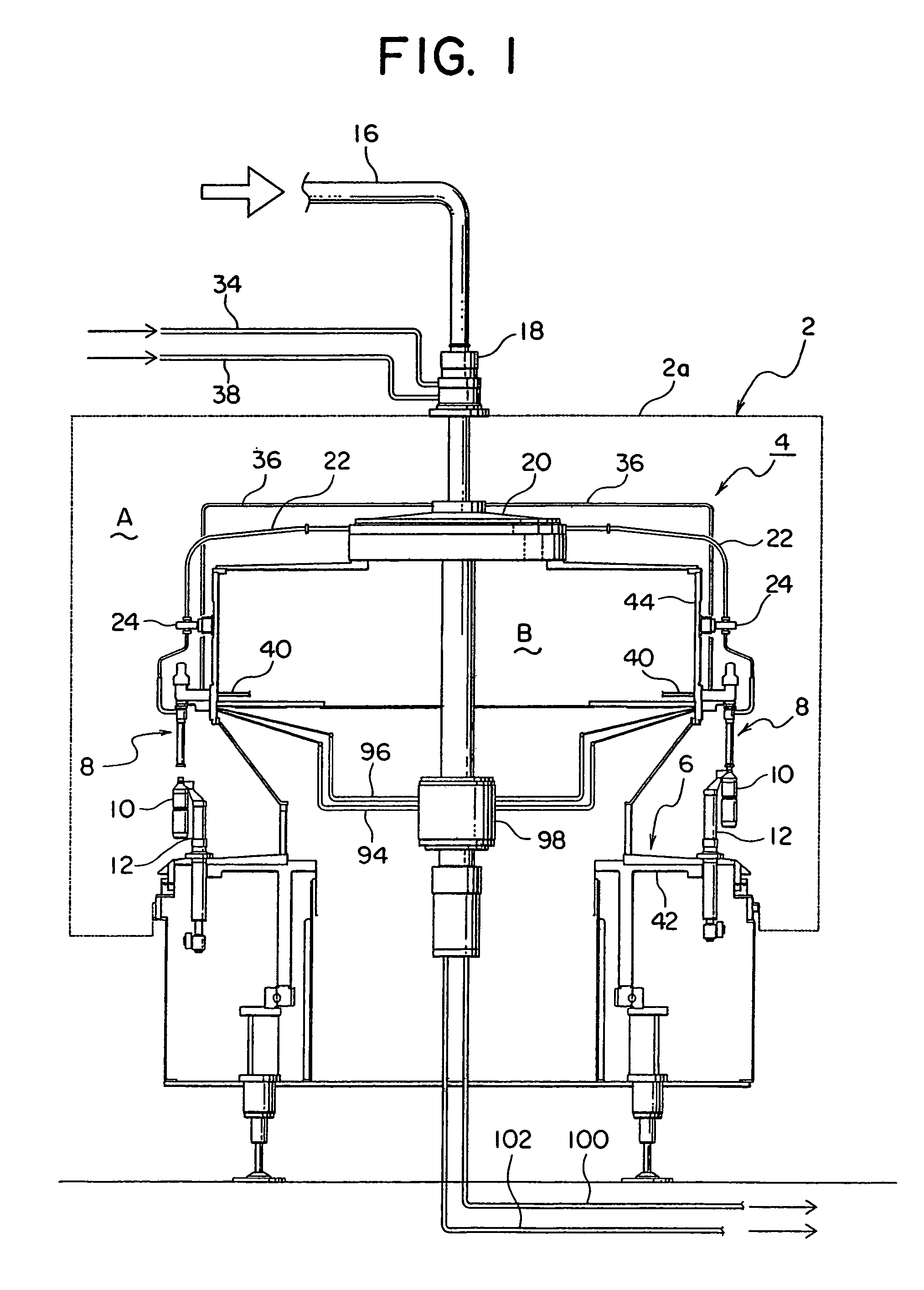
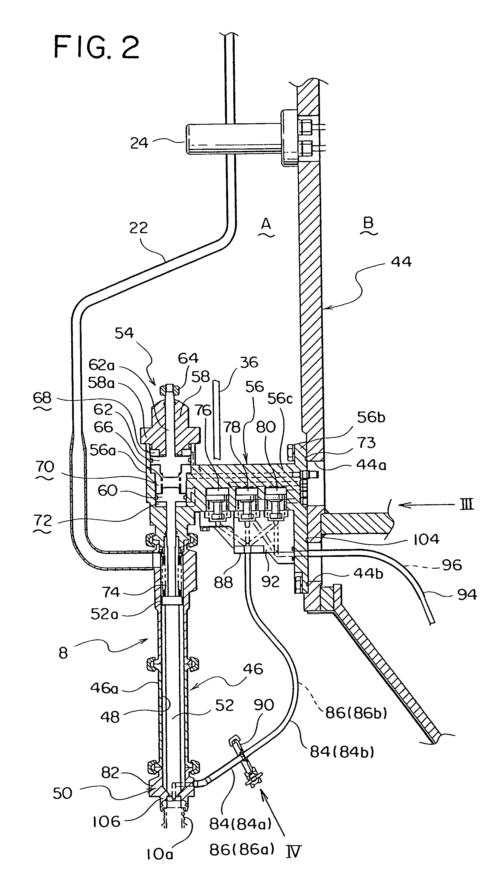
[0014]An embodiment of the present invention shown in the drawings will now be described. A filler including the filling valve according to the present embodiment comprises a rotary filler body, generally indicated by numeral 4, disposed within a space which is enclosed by a stationary external wall 2 and purified to a high level, and a reservoir tank of filled liquid, not shown, disposed outside the external wall 2 for supplying a filled liquid to the rotary filler body 4.

[0015]The filler body 4 includes a plurality of filling valves 8 disposed around the outer periphery of a revolving body 6 at an equal interval circumferentially. Disposed below each filling valve 8 is a vessel holding means 12 which holds and elevates a vessel 10, the vessel holding means 12 elevating the vessel 10 which it holds while rotating integrally with the filling valve 8 and while maintaining a vertical alignment therewith. In the present embodiment, the vessel 10 into which a liquid is to be filled comp...


PUM

PropertyMeasurementUnit
weightaaaaaaaaaa
flow rateaaaaaaaaaa
diameteraaaaaaaaaa

Abstract

A valve housing which is internally formed with a filled liquid passage and a liquid valve which allows or interrupts a communication of the filled liquid passage are provided, and a liquid valve opening / closing air cylinder opens or closes the liquid valve to perform a filling operation of a filled liquid. An outlet portion located at the bottom end of the valve housing is formed by a separate liquid outlet member. A first liquid outlet member which is connected with a gas exhaust passage and used for a carbonated filling operation and a second liquid outlet member which carries a screen on its bottom end and used for a non-carbonated filling operation are interchangeably used. A filling valve which permits a combined use with a carbonated filling operation and a non-carbonated filling operation enables an accommodation for a filling operation which should take place in a clean environment.

Description

BACKGROUND OF THE INVENTION AND RELATED ART[0001]The present invention relates to a filling valve which permits a combined use in a filling of a carbonated beverage and a filling of a non-carbonated beverage, and in particular, to a filling valve which is suitable for a filling operation under a clean environment.[0002]A filling valve which permits a combined use in a filling of a carbonated beverage and a filling of a non-carbonated beverage is known in the art (see, for example, Japanese Laid-Open Patent Application No. 2004-136927). The filling valve disclosed therein comprises a valve housing which is centrally formed with a filled liquid passage communicating with a filled liquid supply piping extending from a tank of filled liquid and which includes a bottom end in which a filling nozzle is mounted. A communication of the filled liquid passage is allowed or interrupted by opening or closing a liquid valve. The filling valve also comprises a bottle mouth gasket which seals the ...

Claims


Application Information

Patent Timeline
Patent Type & Authority Patents(United States)
IPC IPC(8): B65B31/00
CPCB67C3/04B67C3/06B67C3/20B67C3/2614B67C3/28B67C2003/2602B67C2003/2671
Inventor NISHINO, YUKINOBUKAMORI, SHINYASHIMODE, TOORUTSUKANO, KENICHI
Owner SHIBUYA IND CO LTD
Why Eureka
Try Eureka