Flying arrangement

a flying arrangement and amusement park technology, applied in the field of amusement park rides, can solve the problem that the driver cannot determine the course of the event on his own, and achieve the effect of excluding the risk of collisions

Inactive Publication Date: 2008-12-16
DIETER WAGELS
View PDF27 Cites 57 Cited by
  • Summary
  • Abstract
  • Description
  • Claims
  • Application Information

AI Technical Summary

Benefits of technology

[0022]It is recommended that, to exclude the risk of collisions, at least one flying u

Problems solved by technology

The known flying arrangements, however, are constructed in such a manner that the participant or user does not have the opportunity to be actively in

Method used


Image

  • Flying arrangement
  • Flying arrangement
  • Flying arrangement

Examples


Embodiment Construction

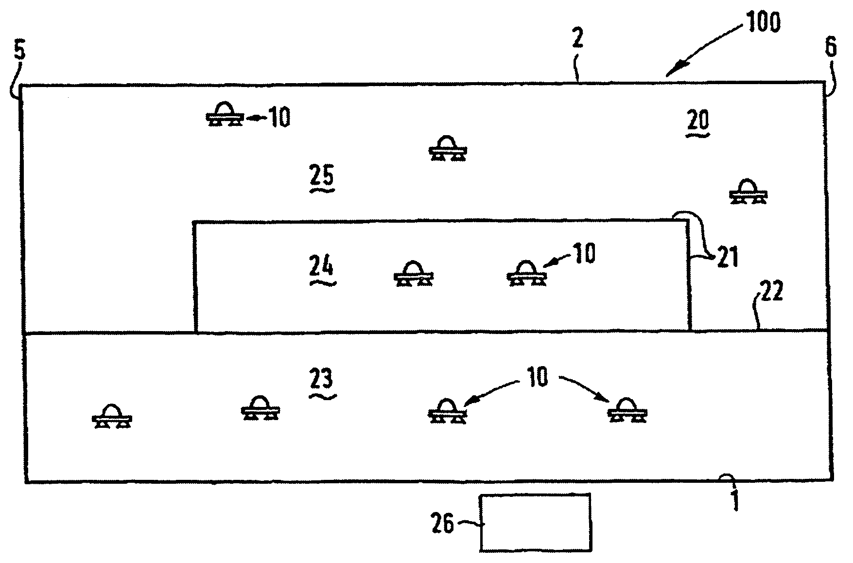
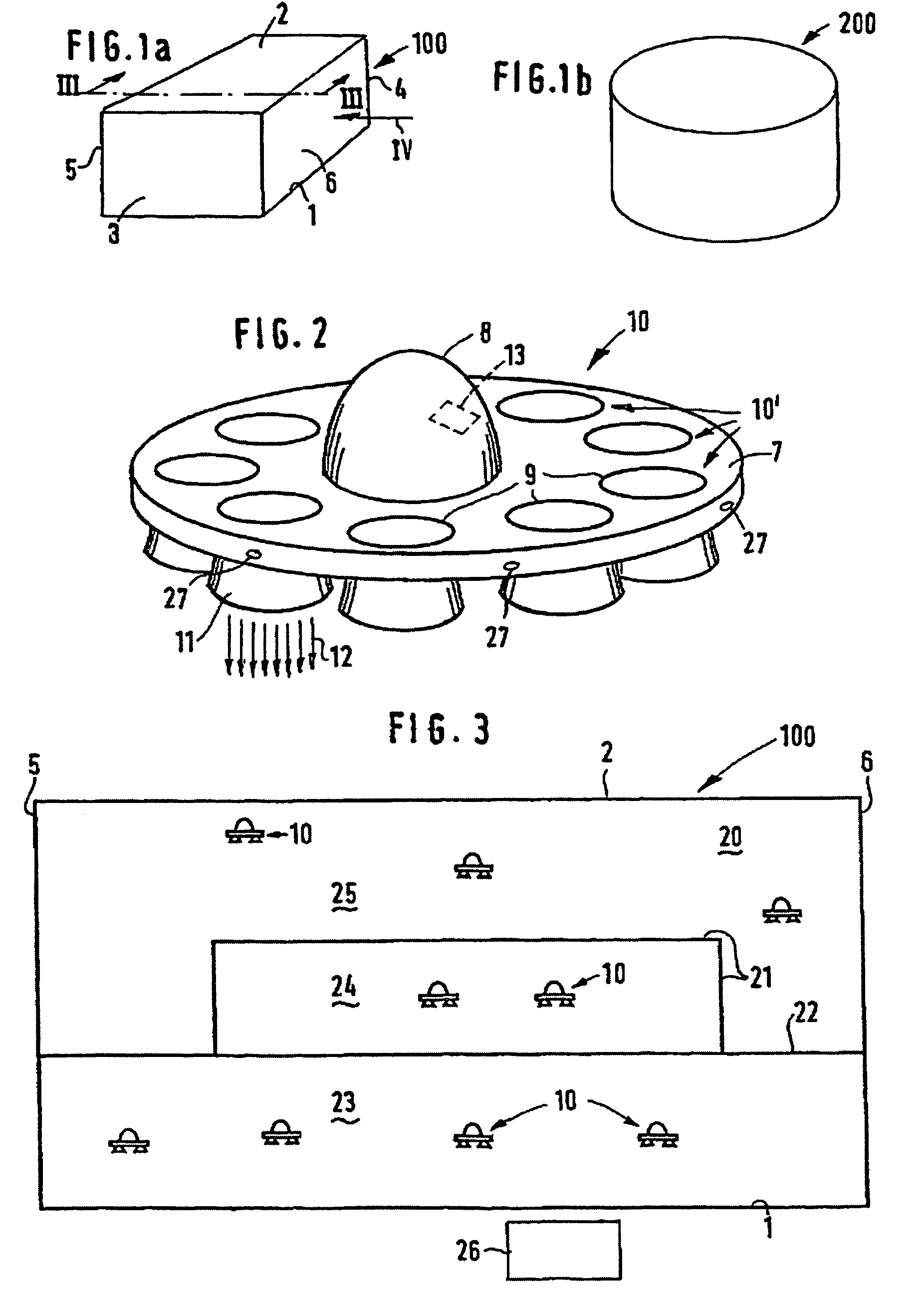
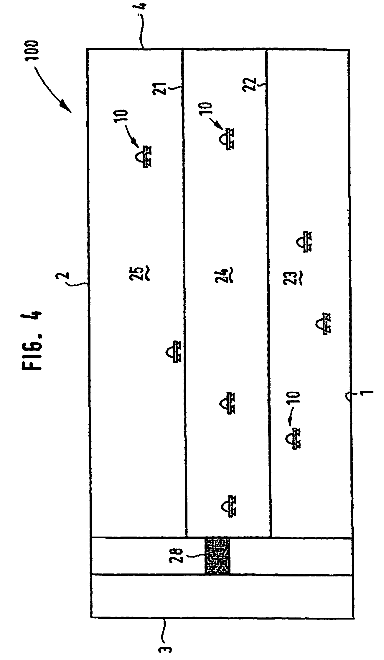
[0029]The hall, which in its entirety is designated by 100 in FIG. 1a, has a rectangle shape with a ground 1, a ceiling 2, two shorter rectangular side faces 3 and 4 and two longer side faces 5 and 6. Side faces 2 to 6 form boundaries that can be designed as closed walls, thus preventing the flying units 10 (FIG. 2) flying inside said hall from leaving hall 100, or as “electronic walls” that interact with the control of flying unit 10, so as to prevent said flying unit from leaving the rectangular space.

[0030]The rectangular shape is only one specific practical example. FIG. 1b shows an alternative practical example 200 of a hall that has the shape of an upright cylinder section, FIG. 5 shows hall 300 that is designed in the form of a flying tunnel assembly 40.

[0031]FIG. 2 shows one single flying unit 10 which, in this particular practical example, is designed in the form of a flying disk and comprises a platform 7 with a circular cross section, in the center of which a cupola 8 mad...


PUM


Abstract

A flying arrangement, consisting of at least one flying unit (10) that is able to start vertically and that can accommodate at least one person for flying freely within at least a hall (100,200), the boundaries (2,3,4,5,6) of which prevent a flying unit (10) from leaving the hall (100,200,300).

Description

CROSS-REFERENCE TO RELATED APPLICATIONS[0001]This application is a national stage entry of international application number PCT / EP2003 / 010659, having international filing date Sep. 25, 2003, which was not published in English, and which claims priority to German patent application No. DE102 45 351.9, filed Sep. 27, 2002.FIELD OF THE INVENTION[0002]The invention relates to amusement rides and more particularly to flying arrangement amusement park rides.BACKGROUND OF THE INVENTION[0003]Amusement park rides that give the participant a feeling of being airborne or of flying are known as carnival attractions. The known flying arrangements, however, are constructed in such a manner that the participant or user does not have the opportunity to be actively involved while he uses such amusement park rides. Instead, he is forced to sit in a seat which is forcibly controlled and follows a fixed path, e.g., on rails as on a roller coaster, on a vertical column or on rods. Thus, the participant ...

Claims


Application Information

Patent Timeline
IPC IPC(8): A63G31/16A63G1/00A63G31/00B64C39/00
CPCA63G31/00B64C39/001
Inventor WAGELS, DIETER
Owner DIETER WAGELS
Why Eureka
Try Eureka