Wheel assembly with electric power generator

Active Publication Date: 2008-12-16
VANCEA PETER
View PDF19 Cites 40 Cited by
  • Summary
  • Abstract
  • Description
  • Claims
  • Application Information

AI Technical Summary

Problems solved by technology

Most automobiles in use today are propelled by gasoline or diesel internal combustion engines, which are known to cause air pollution and contribute to climate change and global warming.
However, the building of battery-powered vehicles that could rival internal combustion models came about only through the advent of modern semiconductor controls.
However, rechar

Method used


Image

  • Wheel assembly with electric power generator
  • Wheel assembly with electric power generator
  • Wheel assembly with electric power generator

Examples


Embodiment Construction

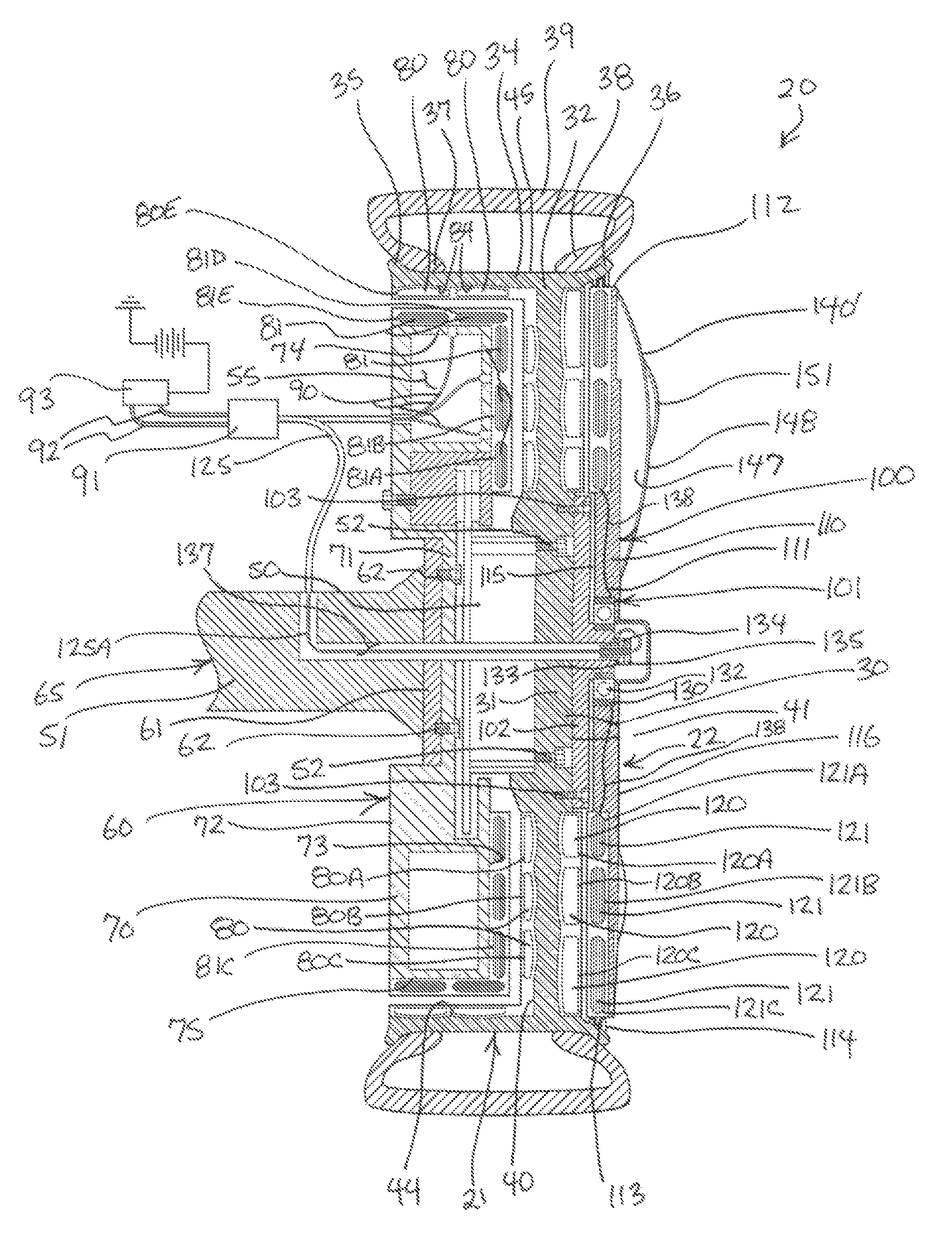
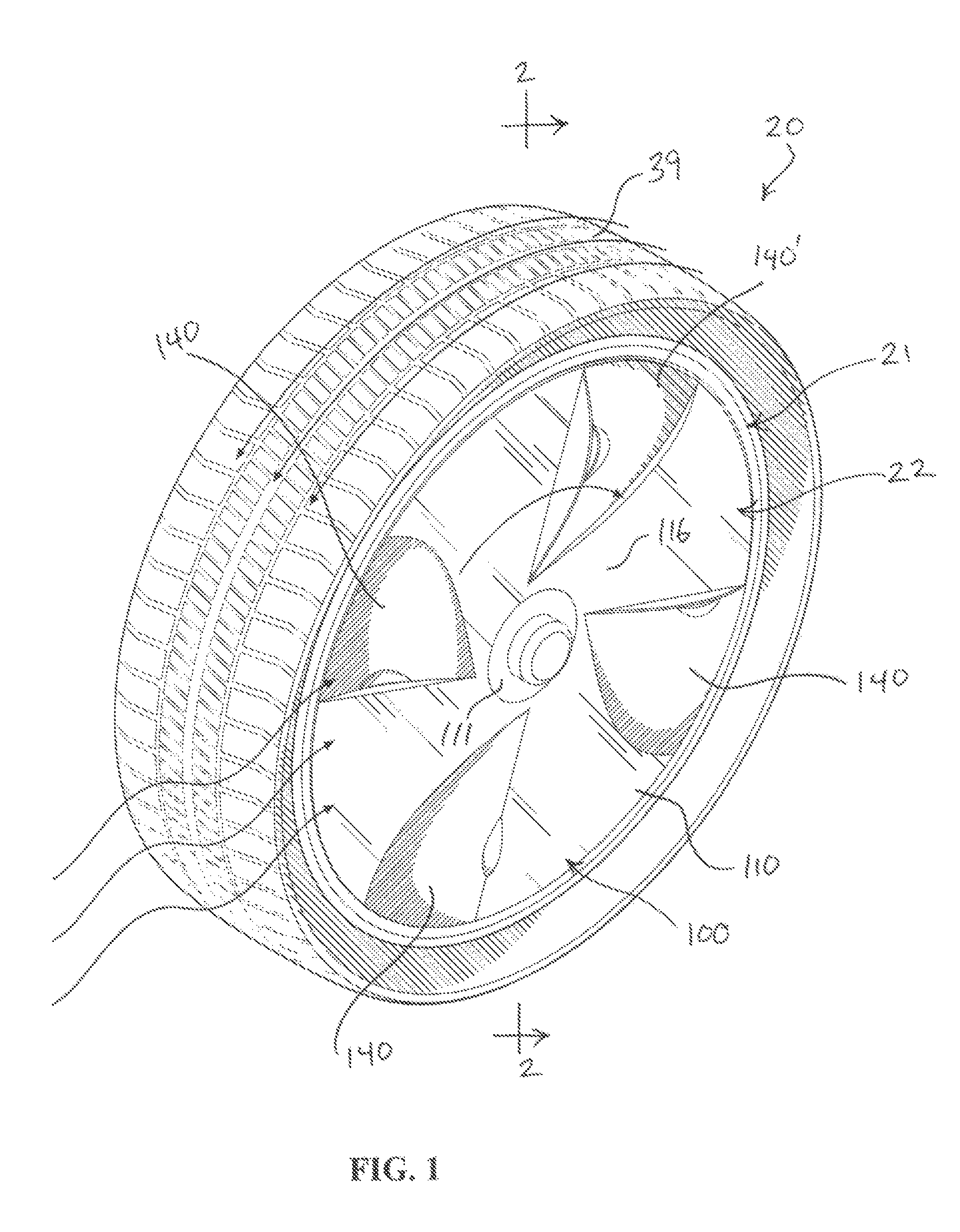
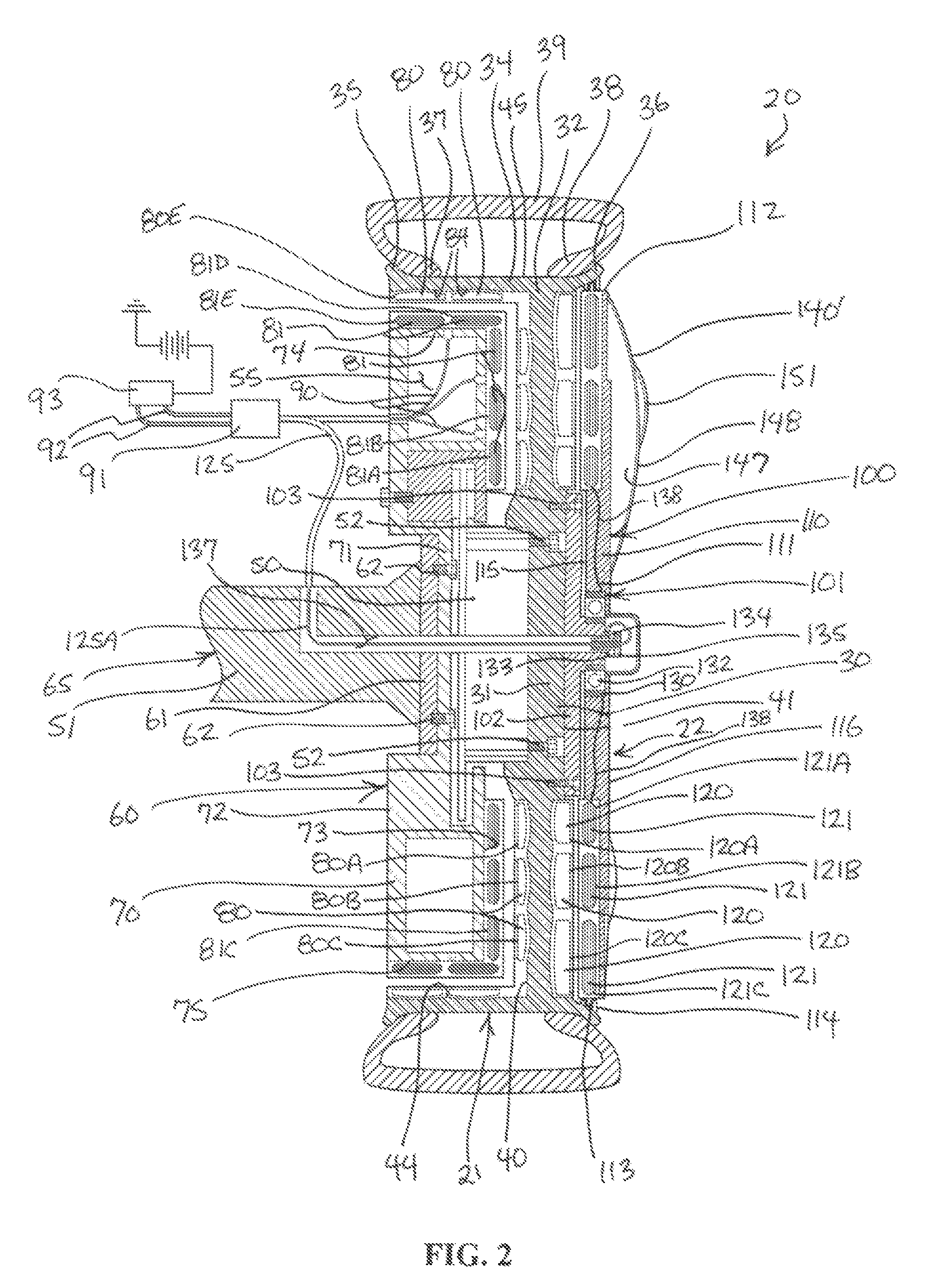
[0026]Turning now to the drawings, in which like reference characters indicate corresponding elements throughout the several views, attention is first directed to FIG. 1 in which there is seen a wheel assembly constructed and arrange in accordance with the principle of the invention and generally designed by the reference character 20. Wheel assembly 20 consists of a wheel 21 incorporating an electrical power generator 22 that generates electrical power in response to rotation of wheel 21, in accordance with the principle of the invention.

[0027]Referencing FIG. 2, which is a sectional view taken along line 2-2 of FIG. 1, wheel 21 consists of an upright circular frame 30 including a central hub 31 and a circular outer perimeter edge 32. An annular sidewall 34 is affixed to outer perimeter edge 32, and is substantially perpendicular relative to circular frame 30. Annular sidewall 34 is formed with opposed annular rims 35 and 36 that accept beads 37 and 38, respectively, of a conventio...


PUM


Abstract

A wheel assembly includes a carrier and a wheel mounted adjacent to the carrier for rotation relative to the carrier. A first array of magnets is carried by one of the first side of the wheel and the carrier, and a first array of coils is carried by the other of the wheel and the carrier corresponding to the first array of magnets. A spinner is mounted adjacent to the wheel for rotation relative to the wheel. A second array of magnets is carried by one of the wheel and the carrier, and a second array of coils is carried by the other of the wheel and the spinner corresponding to the second array of magnets.

Description

FIELD OF THE INVENTION[0001]The present invention relates to electric power generators and to wheel assemblies incorporating electric power generators.BACKGROUND OF THE INVENTION[0002]Future energy development faces great challenges due to an increasing world population, demands for higher standards of living, a need for less pollution, a need to avert global warming, and a need for less reliance on fossil fuels. Because reliance on traditional sources of energy and energy generation relies in large part on unrenewable fossil fuels, and because it is believed that reliance on fossil fuels cannot adequately meet future energy needs, the need for reliance on renewable energy sources and the development of renewable energy sources are vitally important to ensure future energy needs can be satisfied.[0003]Most automobiles in use today are propelled by gasoline or diesel internal combustion engines, which are known to cause air pollution and contribute to climate change and global warmin...

Claims


Application Information

Patent Timeline
IPC IPC(8): H02K7/10
CPCB60B7/20B60B11/02B60K6/26B60K6/46B60K7/0007B60K25/08H02K7/1846B60K2007/0038B60K2007/0092Y02T10/6217B60Y2410/115Y02T10/62
Inventor VANCEA, PETER
Owner VANCEA PETER
Why Eureka
Try Eureka