Image heating apparatus with related image heating member and heat pipe

a technology of image heating and heating member, which is applied in the direction of electrographic process apparatus, instruments, optics, etc., can solve the problems of excessive increase of temperature at the end portion of a fixing member such as a roller or a belt in an axial direction or width direction, inability to quickly eliminate temperature distribution after continuous passing of small-size recording materials, and caused irregular gloss between the sheet passing portion and the non-sheet passing portion. , to achieve the effect of quick relief of temperature differences

Inactive Publication Date: 2008-12-16
CANON KK
View PDF17 Cites 47 Cited by
  • Summary
  • Abstract
  • Description
  • Claims
  • Application Information

AI Technical Summary

Benefits of technology

[0012]A principal object of the present invention is to provide an image heating apparatus, using a magnetism-adjusted alloy method and a heat pipe method in combination, capable of preventing a non-sheet-passing portion temperature rise and quickly alleviating a difference (distribution) of temperature in a longitudinal direction of an image heating member without causing dryout of a heat pipe.

Problems solved by technology

On the other hand, the induction heating method capable of reducing the WUT is required to solve such a problem that a temperature at an end portion of a fixing member such as a roller or a belt in an axial direction or width direction is excessively increased when a small-size recording material is passed through the fixing member (non-sheet-passing portion temperature rise).
Then, when a large-size recording material is passed through the fixing apparatus before the temperature distribution is eliminated, there has been a possibility that an irregularity in gloss between the sheet passing portion and the non-sheet-passing portion is caused to occur.
As a result, there has arisen such a problem that the temperature distribution occurring after the continuous passing of the small-size recording material cannot be eliminated quickly.

Method used


Image

  • Image heating apparatus with related image heating member and heat pipe
  • Image heating apparatus with related image heating member and heat pipe
  • Image heating apparatus with related image heating member and heat pipe

Examples


embodiment 1

(1) Example of Image Forming Apparatus

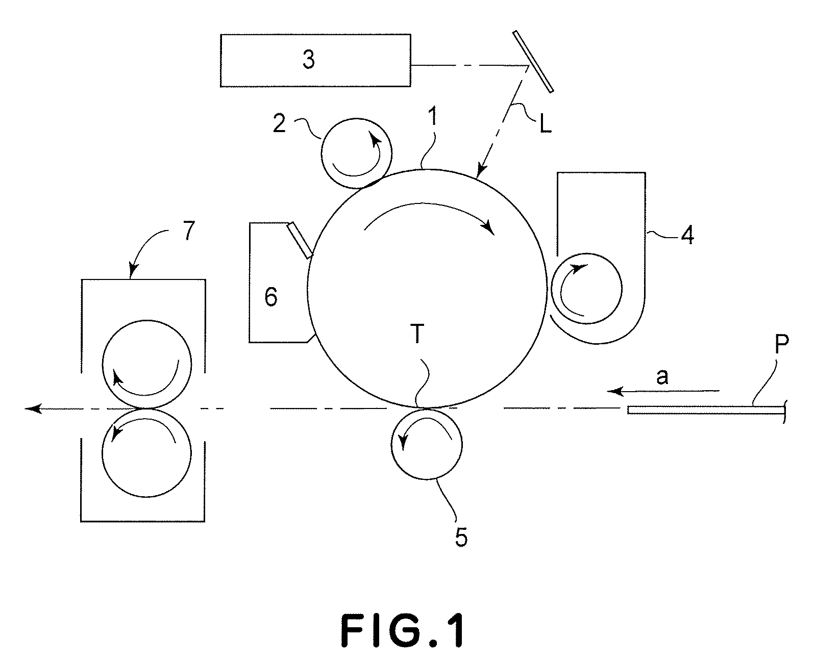
[0039]FIG. 1 is a schematic view showing an example of an image forming apparatus employing an image heating apparatus, as fixing apparatus, in accordance with the present invention, showing the general structure thereof. An image forming apparatus 100 of this embodiment is a laser printer, which uses a transfer-type electrophotographic process.

[0040]Designated by referential numeral 1 is a rotation drum-type electrophotographic photosensitive member (hereinafter referred to as “a photosensitive drum”) as an image bearing member, which is rotationally driven in the clockwise direction indicated by an arrow, at a predetermined peripheral speed.

[0041]Designated by a referential numeral 2 is a charge roller, as a charging means, of the contact type, which uniformly charges electrically an outer peripheral surface of the rotating photosensitive drum 1 to predetermined polarity and potential level.

[0042]Designated by a referential numeral 3 is a lase...

embodiment 2

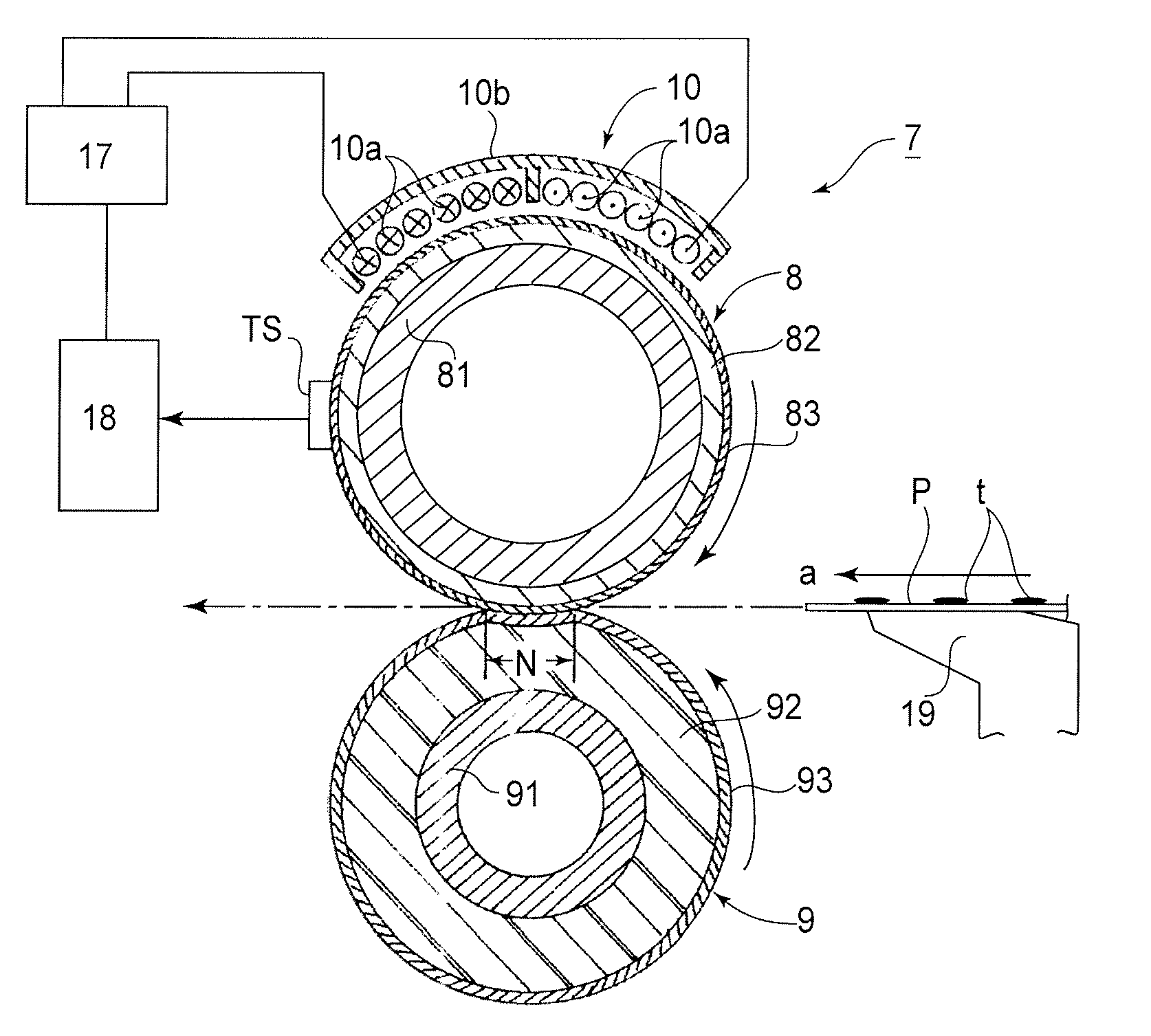
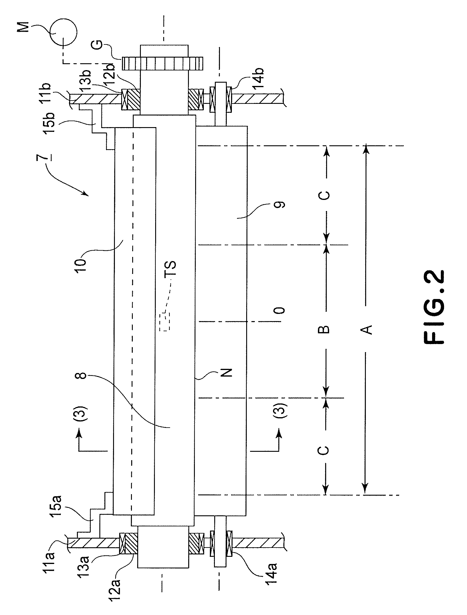
[0132]FIG. 10 is a schematic front view of a principal portion of a fixing apparatus 7 in this embodiment. The fixing apparatus 7 is of a belt fixation type.

[0133]Referring to FIG. 10, the fixing apparatus 7 includes an endless belt (hereinafter referred to as a “fixing belt”) 21 for heating an image on a recording material and another endless belt (hereinafter referred to as a “pressing belt”) 22 for creating a nip between it and the fixing belt 21. The fixing belt 21 is extended and stretched by a fixing roller 23 and a heating roller 8. The pressing belt 22 is extended and stretched by a backup roller 24 and a tension roller 25. The fixing belt 21 and the pressing belt 22 are disposed in such a manner that they contact each other so that a nip is created between a lower surface of the fixing belt 21 and an upper surface of the pressing belt 22. More specifically, a fixing nip (primary nip) Nb is created between the fixing roller 23 and the backup roller 24 via the fixing belt 21 ...


PUM


Abstract

An image heating apparatus includes a coil for generating magnetic flux and an image heating member. The image heating member comprises an electroconductive layer which generates heat by eddy current generated by the magnetic flux from the coil, for heating an image on a recording material. The image heating apparatus further comprises an energization control device for controlling energization of the coil so that a temperature of the image heating member is a predetermined temperature Tf (° C.), and a heat pipe contactable with the image heating member. The electroconductive layer has a Curie temperature Tc so that the relation Tf≦Tc≦Tf+Qmax (W)×Rh (° C. / W) is satisfied, wherein Qmax (W) represents a maximum amount of heat transport, and Rh (° C. / W) represents a value of heat resistance of the heat pipe at a dryout occurrence temperature of the heat pipe.

Description

FIELD OF THE INVENTION AND RELATED ART[0001]The present invention relates to an image heating apparatus, such as a fixing apparatus for fixing an unfixed image on a recording material or a gloss-increasing apparatus for increasing gloss of an image by heating the image fixed on a recording material.[0002]In the following description, a sheet (paper) width of a recording material is a dimension of the recording material in a direction perpendicular to a recording material conveyance direction. A large-size recording material is a recording material, having a maximum sheet width, capable of passing through the image heating apparatus. A small-size recording material is a recording material having a sheet width smaller than that of the large-size recording material. An axial direction, a longitudinal direction, a width direction, or width of respective constitutional members of the apparatus are directions parallel to a direction perpendicular to the recording material conveyance direc...

Claims


Application Information

Patent Timeline
Patent Type & Authority Patents(United States)
IPC IPC(8): G03G15/20
CPCG03G15/2039G03G2215/2009G03G2215/2032G03G2215/2016
Inventor MATSUURA, DAIGOHAYASHI, YASUHIRONAKAMOTO, IKUOHASEGAWA, KAZUHIROTAKADA, SHIGEAKI
Owner CANON KK
Why Eureka
Try Eureka