Fuselage mounted evacuation slide system

a slide system and fuselage technology, applied in the direction of chutes, aircraft ejection means, building rescue, etc., can solve the problem of easy tearing of the evacuation slide on the edge of the fuselage opening

a slide system and fuselage technology, applied in the direction of chutes, aircraft ejection means, building rescue, etc., can solve the problem of easy tearing of the evacuation slide on the edge of the fuselage opening

US7467764B2Active Publication Date: 2008-12-23THE BF GOODRICH CO

Image

  • Fuselage mounted evacuation slide system
  • Fuselage mounted evacuation slide system
  • Fuselage mounted evacuation slide system

Examples


Embodiment Construction

[0015]The drawing figures are intended to illustrate the general manner of construction and are not necessarily to scale. In the detailed description and in the drawing figures, specific illustrative examples are shown and herein described in detail. It should be understood, however, that the drawing figures and the detailed description are not intended to limit the invention to the particular form disclosed, but are merely illustrative and intended to teach one of ordinary skill how to make and / or use the invention claimed herein and for setting forth the best mode for carrying out the invention.

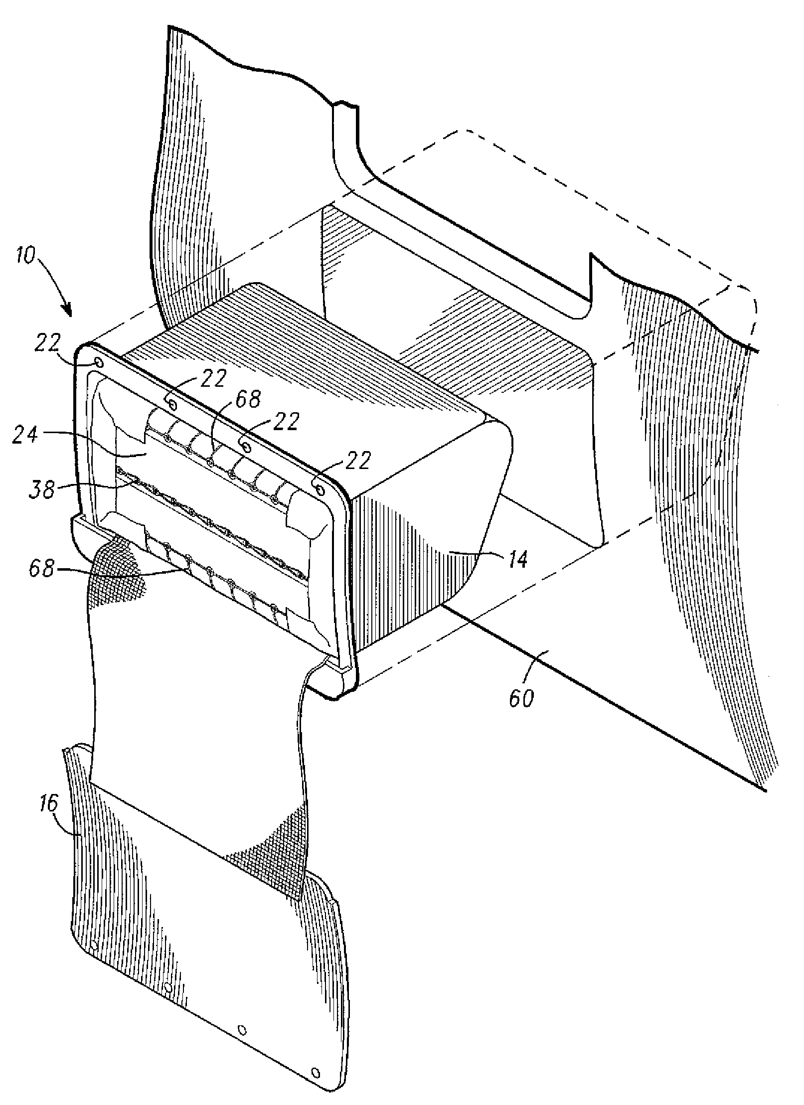
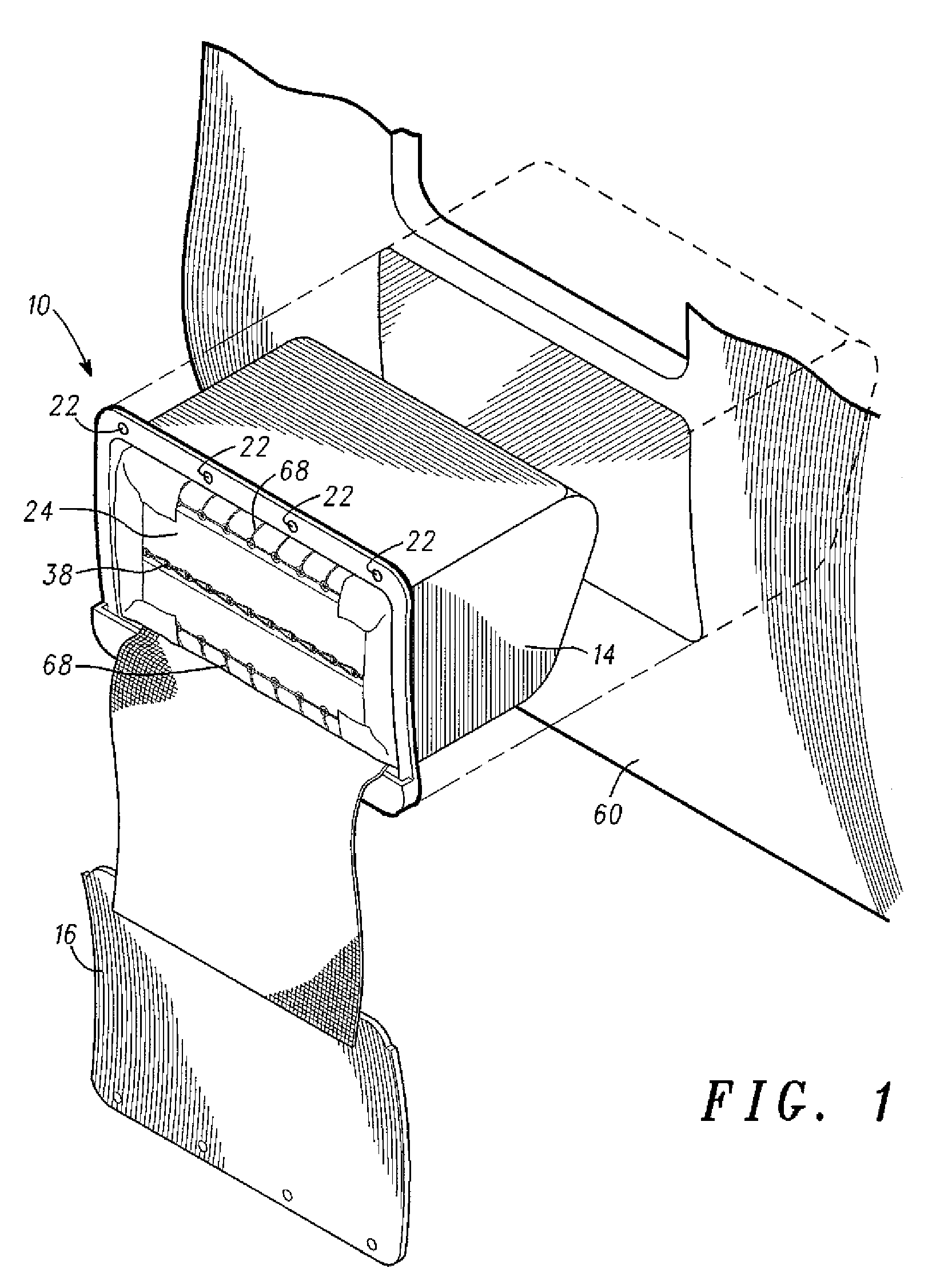
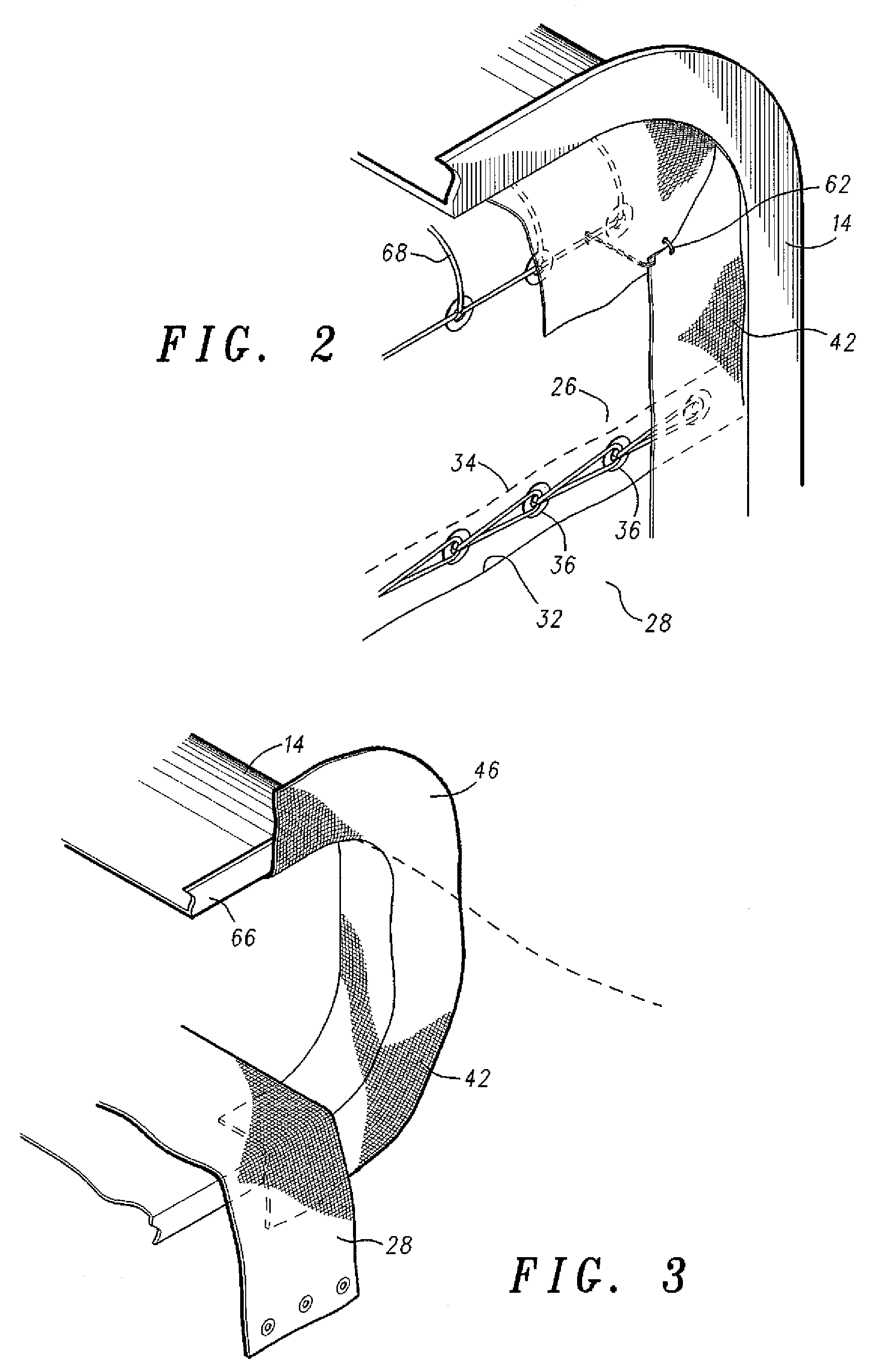
[0016]With reference to FIGS. 1-5, emergency evacuation slide system 10 comprises an inflatable evacuation slide 11 which comprises a conventional flexible panel that defines a slide surface having a head end and a foot end supported by a plurality of inflatable tubular members that extend from the head end toward the foot end of the slide. Inflatable evacuation slide 11 is stored in a fold...


PUM


Abstract

An inflatable evacuation slide system includes a slide pack that is ejected from its enclosure by means of an ejection bag, which inflates rapidly to force the evacuation slide out of the enclosure. The high accelerations imposed on the uninflated evacuation slide by the ejection bag make the slide prone to tearing on the edge of the fuselage as the slide pack is forced through the opening. Accordingly, the enclosure is provided with a chafing skirt, which comprises a flexible collar that deploys outward from the enclosure and lays flat against the aircraft fuselage to provide a smooth transition region between the enclosure and the aircraft skin.

Description

BACKGROUND OF THE INVENTION[0001]The present invention relates to emergency evacuation equipment for aircraft, in particular to inflatable aircraft evacuation slides.[0002]The requirement for reliably evacuating airline passengers in the event of an emergency is well-known. A conventional method of quickly evacuating a large number of passengers from an aircraft is to provide multiple emergency exits, each of which is equipped with an inflatable evacuation slide. Door-mounted emergency evacuation slides are typically contained within an enclosure mounted to the interior surface of the aircraft exit door. Opening of the door in the “armed” position causes the slide to be pulled downward out of the enclosure into a position immediately outboard of and below the door exit opening. The evacuation slide is then rapidly inflated to form a structure sufficiently rigid to enable the airline passengers to escape. Over-wing evacuation slides are typically mounted outside the pressurized aircr...

Claims


Application Information

Patent Timeline
23 Dec 2008
Publication
US7467764B2
IPC
B64C1/12
CPC
B64D25/14
Inventors
HINTZMAN, ROLAND D.