Turbine blade including revised platform

a turbine blade and platform technology, applied in the field of turbine blades, can solve the problems of thermal-mechanical stress addition of the turbine blade, the need to operate in an extremely harsh environment, and the traditional coating does not provide adequate protection against stress corrosion, so as to reduce mechanical and environmental stress factors

Active Publication Date: 2008-12-23
RTX CORP
View PDF13 Cites 23 Cited by
  • Summary
  • Abstract
  • Description
  • Claims
  • Application Information

AI Technical Summary

Benefits of technology

[0007]The present invention provides a turbine blade having a revised under-platform structure, including a novel coating process and a configuration that reduces mechanical and environmental stress factors within the turbine blade.
[0008]The turbine blade includes a platform with an airfoil extending upwardly from the platform and a root portion extending downwardly from the platform. The turbine blade has a pressure side and a suction side. Two suction side tabs extend a first distance outwardly from the suction side of the root portion below the platform. Two pressure side tabs extend outwardly from the pressure side of the root portion below the platform. One of the two pressure side tabs extends outwardly a distance similar to the first distance, however, the other of the two pressure side tabs extends outwardly a second distance that is significantly less than the first distance. The shorter of the two pressure tabs regionally decreases mechanical stress factors within the turbine blade.
[0009]In addition, a plurality of coatings are systematically placed and layered to reduce mechanical and environmental stress factors. A first coating is applied to substantially cover the turbine blade on both sides of the platform. The first coating protects against corrosion in areas of low stress concentration. However, the area under the platform of the turbine blade at the root portion is subjected to much higher stress concentrations than other areas of the turbine blade. Therefore, a second coating is applied over the first coating only under the platform. The second coating is added to resist corrosion cracking in areas of high stress concentration. The second coating is applied using a line-of-sight coating process through an access area that is created as a result of the shortened pressure side tab. The second coating is applied underneath the platform by spraying the coating directly at the shorter of the two pressure side tabs. Additional coatings are applied to the turbine blade to further reduce the effects of stress.

Problems solved by technology

In addition, the turbine blades are typically cooled using relatively cool air bled from the compressor resulting in temperature gradients being formed, which can lead to additional elements of thermal-mechanical stress within the turbine blades.
Further, because the turbine blades are located downstream of the combustor where fuel and air are mixed and burned in a constant pressure process, they are required to operate in an extremely harsh environment.
The traditional coating protects primarily against stress corrosion in areas of low stress concentration, however, the traditional coating does not provide adequate protection against stress corrosion in areas of high stress concentration, for example, under the platform.

Method used


Image

  • Turbine blade including revised platform
  • Turbine blade including revised platform
  • Turbine blade including revised platform

Examples


Embodiment Construction

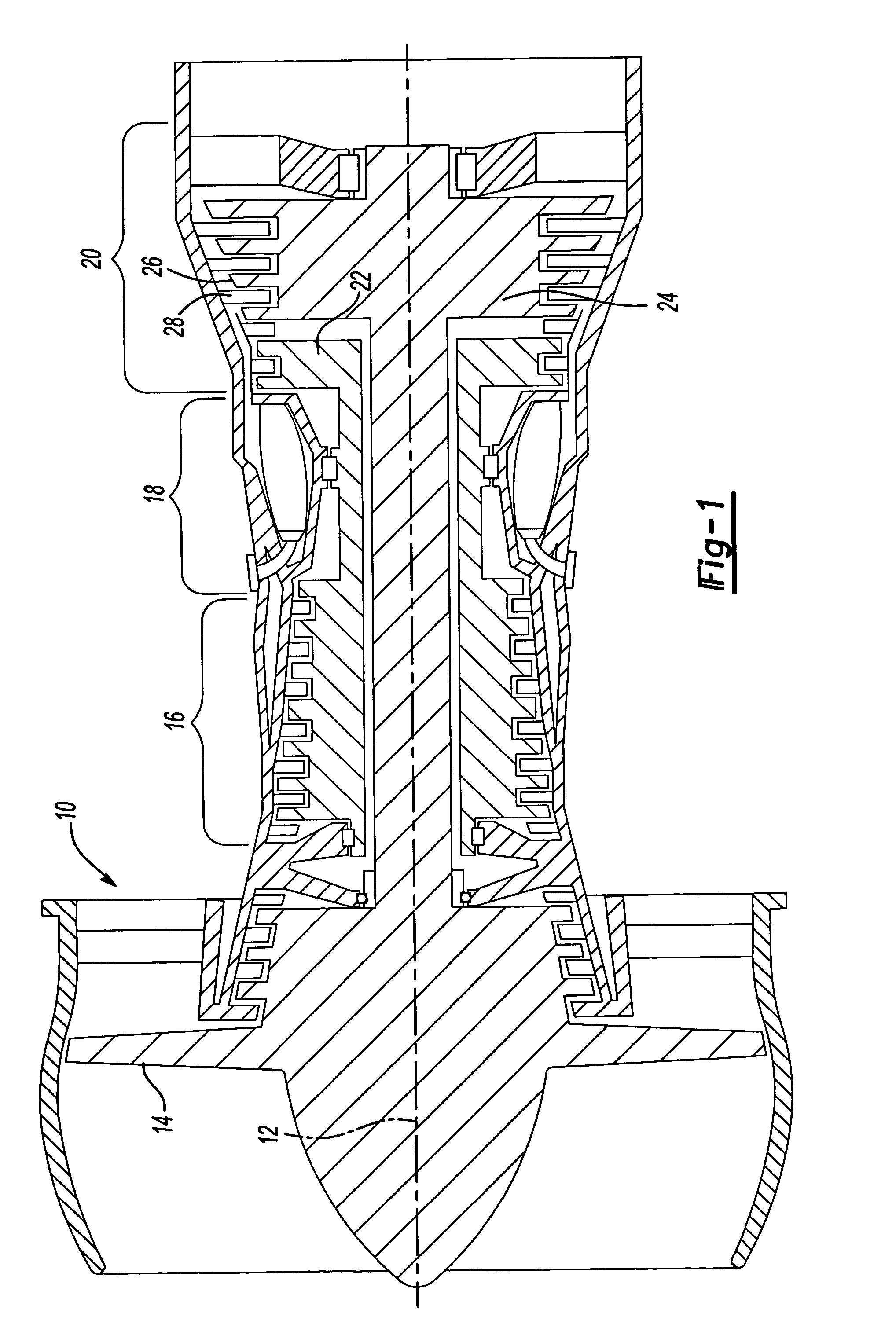
[0017]FIG. 1 is a schematic illustration of an example gas turbine engine 10 circumferentially disposed about an engine centerline, or axial centerline axis 12. The example gas turbine engine 10 includes a fan 14, a compressor 16, a combustor 18, and a turbine assembly 20. As is known, intake air from the fan 14 is compressed in the compressor 16, the compressed air is mixed with fuel that is burned in the combustor 18 and expanded in the turbine assembly 20. The turbine assembly 20 includes rotors 22 and 24 that, in response to the expansion, rotate, driving the compressor 16 and the fan 14. The turbine assembly 20 includes alternating rows of rotary blades 26 and static airfoils or vanes 28, which are mounted to the rotors 22 and 24. The example gas turbine engine 10 may, for example, be a gas turbine used for power generation or propulsion. However, this is not a limitation on the present invention, which may be employed on gas turbines used for electrical power generation, in ai...


PUM

PropertyMeasurementUnit
pressureaaaaaaaaaa
lengthaaaaaaaaaa
circumferenceaaaaaaaaaa

Abstract

The present invention provides a turbine blade having a revised under-platform structure including a unique coating combination that reduces mechanical stress factors within the turbine blade. The turbine blade includes a platform with an airfoil extending upwardly from the airfoil and a root portion extending downwardly from the platform. Two suction side tabs extend a first distance outward from a suction side of the root potion. Two pressure side tabs extend outward from a pressure side of the root portion. One of the two pressure side tabs extends outward a distance similar to the first distance, however, the other of the two pressure side tabs extends outward a distance much smaller than the first distance, which reduces stresses acting on the turbine blade. In addition, a plurality of coatings are systematically applied to the turbine blade to further reduce mechanical stress factors and improve cooling.

Description

BACKGROUND OF THE INVENTION[0001]This application relates generally to a turbine blade for a gas turbine engine wherein a tab structure under the platform is modified.[0002]Conventional gas turbine engines include a compressor, a combustor and a turbine assembly that has a plurality of adjacent turbine blades disposed about a circumference of a turbine rotor. Each turbine blade typically includes a root that attaches to the turbine rotor, a platform, and a blade that extends radially outwardly from the turbine rotor.[0003]The compressor receives intake air. The intake air is compressed by the compressor and delivered primarily to the combustor where the compressed air and fuel are mixed and burned in a constant pressure process. A portion of the compressed air is bled from the compressor and fed to the turbine to cool the turbine blades.[0004]The turbine blades are used to provide power in turbo machines by exerting a torque on a shaft that is rotating at a high speed. As such, the ...

Claims


Application Information

Patent Timeline
Patent Type & Authority Patents(United States)
IPC IPC(8): F01D5/10
CPCF01D5/22F01D5/3007F05D2230/31F05D2300/132
Inventor CHARBONNEAU, ROBERT A.BOTTICELLO, KENNETH P.GREGG, SHAWN J.HLAVATY, KIRK DAVIDLEVINE, JEFFREY R.LONCZAK, KENNETH A.MCGARRAH, CRAIG R.MONGILLO, DOMINIC J.O'NEILL, LISA P.PIETRASZKIEWICZ, EDWARDSALZILLO, RICHARD M.TERRY, HEATHER ANN
Owner RTX CORP
Why Eureka
Try Eureka