Multiple condenser reheat system with tandem compressors

a technology of tandem compressors and condensers, which is applied in the field of refrigerant systems, can solve the problems of not being used and challenging refrigerant system designers, and achieve the effect of preventing excessive frost formation

Inactive Publication Date: 2008-12-30
CARRIER CORP
View PDF7 Cites 32 Cited by
  • Summary
  • Abstract
  • Description
  • Claims
  • Application Information

AI Technical Summary

Benefits of technology

[0009]The present invention, by providing separate condensers, allows for heat rejection at two different temperature levels and to two different zones. As an example, a first condenser could be associated with an outdoor zone, while the second condenser is associated with an indoor zone that would be preferably at a different temperature. By controlling the temperature at which heat is rejected, the amount of the refrigerant passing from that condenser can be tightly controlled. One possible application would be to utilize one of the condensers to prevent excessive frost formation (defrost operation), with the other condenser being operable in a conventional manner as in normal air conditioning installations. Another possible application is to utilize this invention in heat pump systems where heating of two separate environments requiring different levels of heating is desired. In this case, each condenser can be employed to provide heating to each environment. Many other applications such as air stream reheat in dehumidification applications or space heating are also feasible.
[0010]Integration of the reheat coil into the system design provides the additional flexibility of lowering the temperature of air passing over the evaporator to remove moisture, and then reheating the air back to a desired temperature. Several reheat schemes are disclosed. However, it should be understood that the fundamental concept of this invention is the incorporation of a reheat cycle into a refrigerant system having tandem compressors delivering refrigerant to multiple condensers, preferably operating at different temperature levels, and accepting refrigerant from a common evaporator. The particular refrigerant system provides a wide variety of options for the reheat function in terms of the reheat concept and position of the reheat coil in relationship to the condenser and evaporator.

Problems solved by technology

These opposite trends have presented challenges to refrigerant system designers.
While reheat coils have been incorporated into air conditioning systems, they have not been utilized in an air conditioning system having an ability to operate at multiple temperature levels.

Method used


Image

  • Multiple condenser reheat system with tandem compressors
  • Multiple condenser reheat system with tandem compressors
  • Multiple condenser reheat system with tandem compressors

Examples


embodiment 220

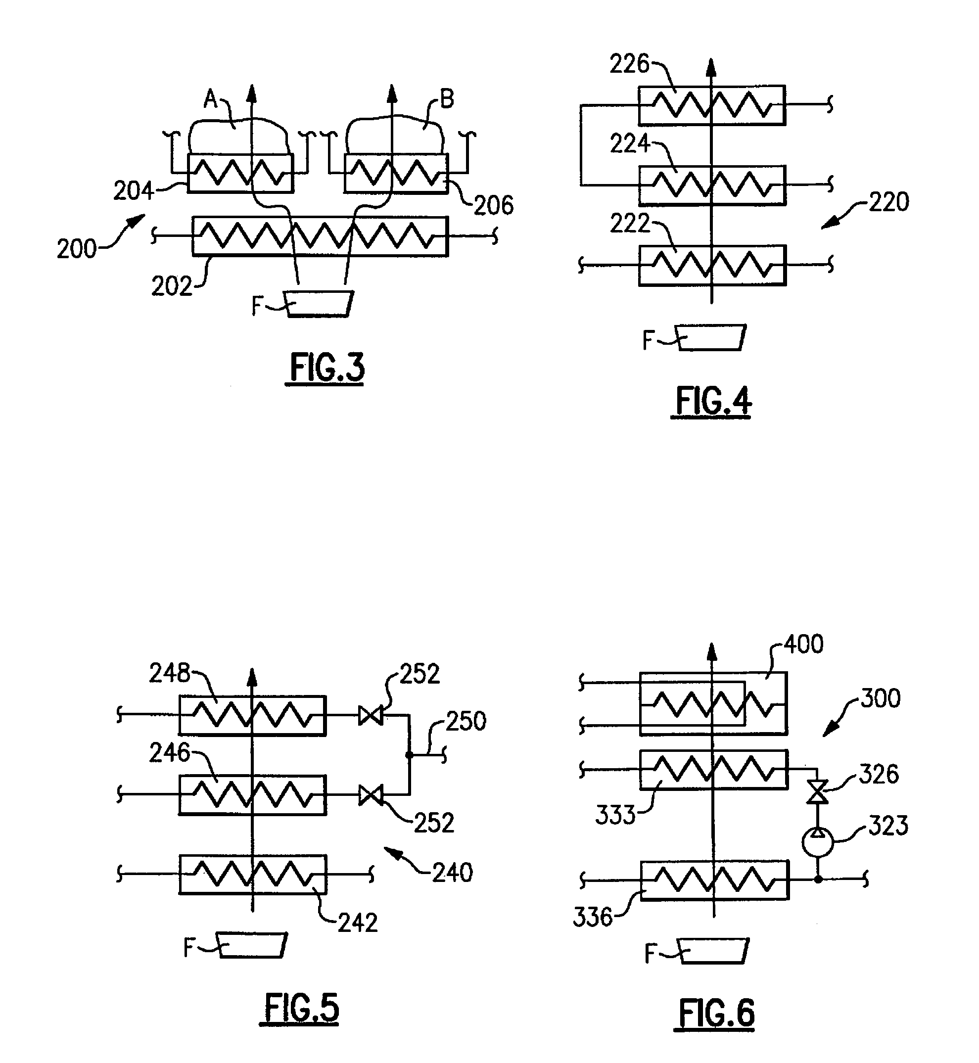
[0031]FIG. 4 shows an embodiment 220, wherein an evaporator 222 is associated with a pair of reheat coils 224 and 226. As can be seen, the reheat coils 224 and 226 are in a serial flow relationship, and receive refrigerant flow from a common point in the refrigerant cycle. Hence, both reheat coils 224 and 226 employ similar reheat concepts, but the refrigerant flowing through each coil would have a different thermodynamic state and consequently would provide different amount of reheat. Obviously, as in the FIG. 3 embodiment, the reheat coils 224 and 226 can be placed side-by-side behind the evaporator 222 to treat separate portions of the airflow.

[0032]FIG. 5 shows a system 240, wherein an evaporator 242 is associated with a pair of reheat coils 246 and 248. As can be seen, a common supply line 250 for the refrigerant flowing into the reheat coils 246 and 248 is utilized, however, the reheat coils 246 and 248 receive the refrigerant in a similar thermodynamic state and in a parallel...

embodiment 300

[0033]Finally, FIG. 6 shows an embodiment 300, wherein an evaporator 336 is associated with a reheat coil 333, and wherein the reheat coil 333 is actually one of the condensers associated with a compressor 322 and a discharge valve 326. Again, the evaporator 336 would be associated with at least one more compressor in this embodiment. Furthermore, one of the condensers (the condenser 333 in this case) utilized as a reheat coil in this embodiment may represent only one of multiple reheat stages (coils) associated with the evaporator 336, and a conventional supplemental reheat coil 400 could also be employed here.

[0034]Notably, the various refrigerant systems disclosed in this application can all be utilized as air conditioning units or as heat pumps.


PUM


Abstract

A tandem compressor system is utilized that receives refrigerant from a common suction manifold, and from a common evaporator. From the compressors, the refrigerant passes to a plurality of condensers, with each of the condensers being associated with a separate zone for heat rejection, preferably at different temperature levels. Each of the condensers is associated with at least one of the plurality of compressors. A reheat coil is associated with the evaporator to improve comfort level in the environment to be conditioned. Multiple reheat circuits associated with separate condensers are employed to provide various stages of reheat or to condition separate environments. By utilizing the common evaporator, a plurality of condensers, and the reheat coils, the ability to independently control temperature, humidity and amount of heat rejection to a number of zones is achieved without the requirement of having dedicated circuits with multiple additional components. Thus, the overall system cost and complexity is significantly reduced and its operational and control flexibility is improved.

Description

BACKGROUND OF THE INVENTION[0001]This application relates to a refrigerant system utilizing tandem compressors sharing a common evaporator, but having separate condensers and wherein a reheat coil is incorporated into the system design.[0002]Refrigerant systems are utilized in applications to change the temperature and humidity or otherwise condition the environment. In a standard refrigerant system, a compressor delivers a compressed refrigerant to a heat exchanger, known as a condenser, which is typically located outside. From the condenser, the refrigerant passes through an expansion device to an indoor heat exchanger, known as an evaporator. In the evaporator, moisture may be removed from the air, and the temperature of air blown over the evaporator coil is lowered. From the evaporator, the refrigerant returns to the compressor. Of course, basic refrigerant cycles are utilized in combination with many configuration variations and optional features. However, the above provides a ...

Claims


Application Information

Patent Timeline
Patent Type & Authority Patents(United States)
IPC IPC(8): F25B41/00
CPCF24F3/153F25B1/10F25B6/02F25B41/04F25B2400/075F25B2600/2507F25B41/20F25B41/24
Inventor TARAS, MICHAEL F.LIFSON, ALEXANDER
Owner CARRIER CORP
Why Eureka
Try Eureka