Cogeneration system

a cogeneration system and cogeneration technology, applied in the field of cogeneration systems, can solve the problems of compressors b>5/b>, the efficiency of cogeneration systems cannot be maximized, etc., and achieve the effect of maximizing the efficiency of the system

Inactive Publication Date: 2006-06-15
LG ELECTRONICS INC
View PDF7 Cites 22 Cited by
  • Summary
  • Abstract
  • Description
  • Claims
  • Application Information

AI Technical Summary

Benefits of technology

[0015] The present invention has been made in view of the above-mentioned problems, and it is an ob

Problems solved by technology

However, the conventional cogeneration system has a problem in that the waste heat of the engine 10 is only used in the heat consumer 30 such as a thermal storage tank without being used to

Method used


Image

  • Cogeneration system
  • Cogeneration system
  • Cogeneration system

Examples


Embodiment Construction

[0039] Hereinafter, exemplary embodiments of a cogeneration system according to the present invention will be described with reference to the annexed drawings.

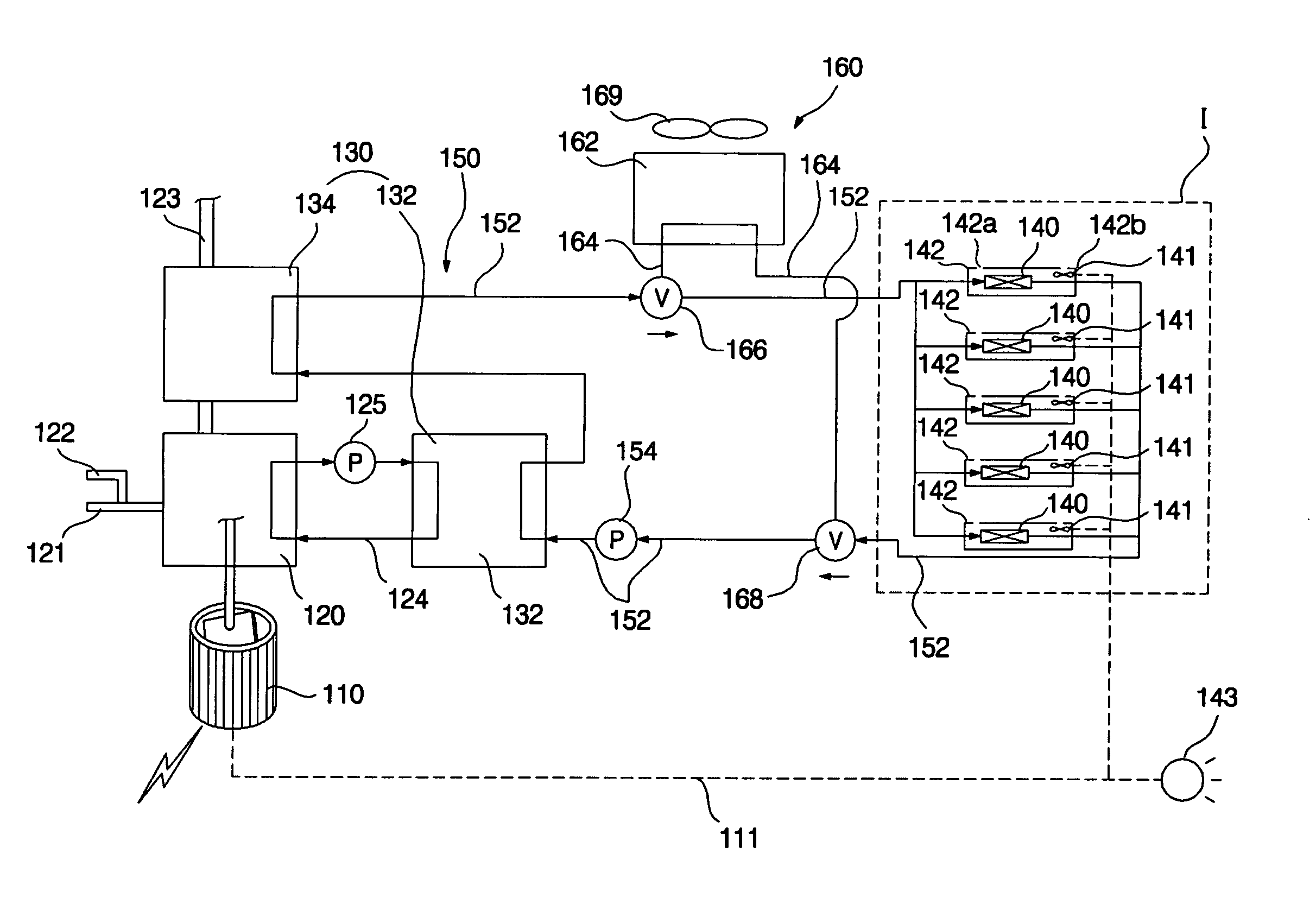
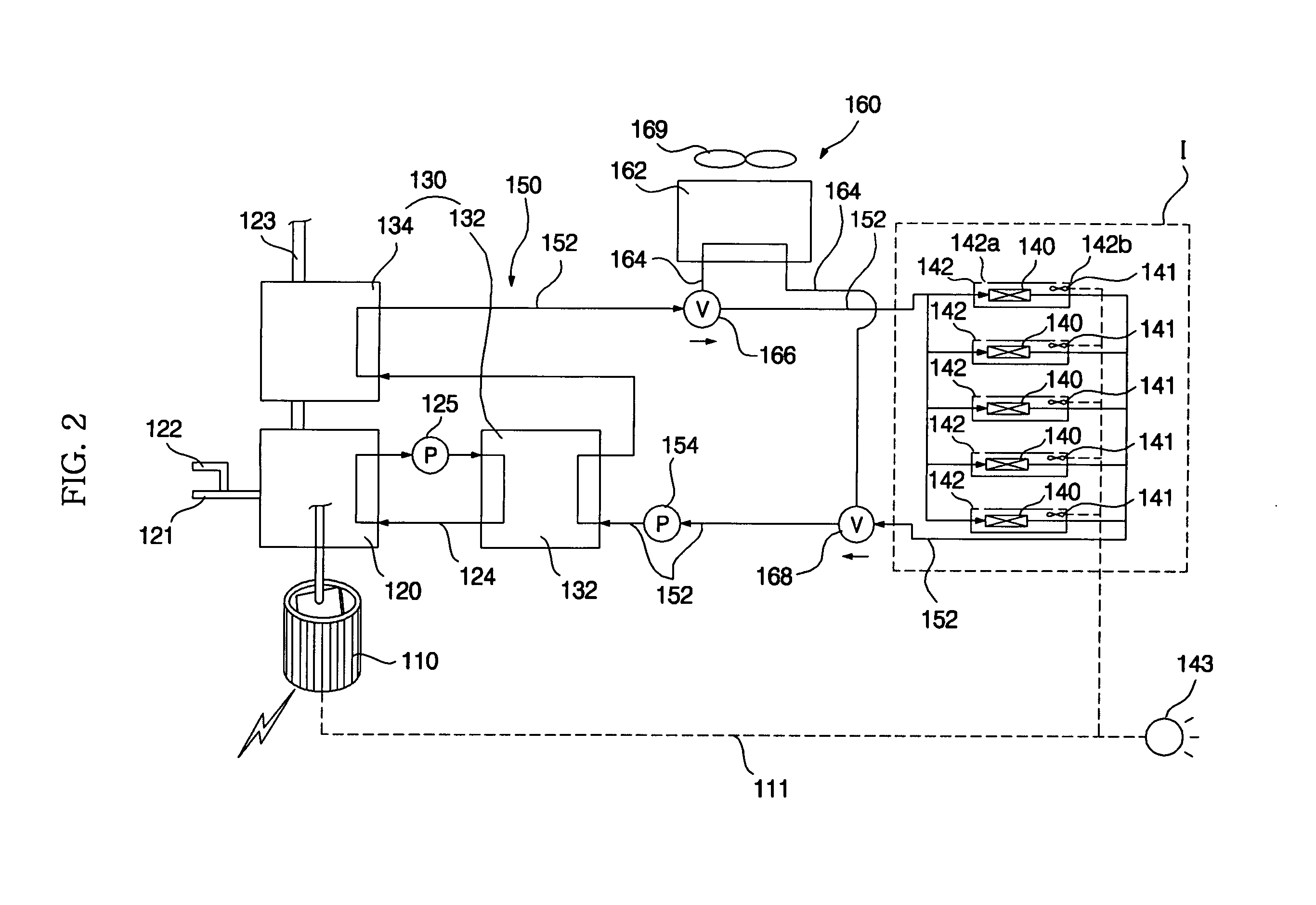
[0040]FIG. 2 is a schematic diagram of a cogeneration system according to a first embodiment of the present invention, illustrating a state in which an indoor space is heated is carried out using heating heat exchangers. FIG. 3 is a schematic diagram of the cogeneration system according to the first embodiment of the present invention, illustrating a state in which waste heat is released to the atmosphere.

[0041] As shown in FIGS. 2 and 3, the cogeneration system according to the first embodiment of the present invention includes a generator 110, a drive source 120 which operates to drive the generator 110, in order to cause the generator 110 to generate electricity, and generates waste heat during the operation thereof, a waste heat recovering heat exchanger 130 which recovers heat from the drive source 120, heating heat exc...


PUM


Abstract

A cogeneration system is disclosed which includes a waste heat recovering heat exchanger for recovering waste heat generated from a drive source when the drive source operates to drive a generator, heating heat exchangers for heating indoor air, and a heat transfer unit for transferring heat from the waste heat recovering heat exchanger to the heating heat exchangers. The waste heat of the drive source can be used to heat indoor air present in an indoor space. Accordingly, it is possible to maximize the efficiency of the cogeneration system, and to heat indoor heat without driving a compressor.

Description

BACKGROUND OF THE INVENTION [0001] 1. Field of the Invention [0002] The present invention relates to a cogeneration system, and, more particularly, to a cogeneration system which can heat indoor air using waste heat of an engine. [0003] 2. Description of the Related Art [0004]FIG. 1 is a schematic view illustrating a conventional cogeneration system. [0005] As shown in FIG. 1, the conventional cogeneration system includes a generator 2 which generates electric power, a drive source 10 which operates to drive the generator 2, and generates waste heat during the operation thereof, such as an engine (hereinafter, the drive source 10 will be referred to as an “engine”), a waste heat recoverer 20 which recovers waste heat generated from the engine 10, and a heat consumer 30 which utilizes the waste heat recovered by the waste heat recoverer 20, such as a thermal storage tank. [0006] The electric power generated from the generator 2 is supplied to various electric home appliances includin...

Claims


Application Information

Patent Timeline
IPC IPC(8): B60H1/02F25B27/00F24D1/04F24D5/00
CPCF02G5/00F25B13/00Y02B30/52Y02E20/14Y02T10/166F25B27/02Y02E60/14Y02T10/12Y02P80/15Y02A30/274F28D20/00
Inventor HA, SIM BOKCHUNG, BAIK YOUNGKO, CHEOL SOOKIM, CHEOL MIN
Owner LG ELECTRONICS INC
Why Eureka
Try Eureka