Refrigerator, and method for controlling operation of the same

a technology for refrigerators and control devices, applied in the field of refrigerators, can solve problems such as power consumption increase, and achieve the effect of reducing power consumption and improving cooling efficiency

Inactive Publication Date: 2005-12-22
LG ELECTRONICS INC
View PDF21 Cites 22 Cited by
  • Summary
  • Abstract
  • Description
  • Claims
  • Application Information

AI Technical Summary

Benefits of technology

[0018] The present invention is achieved to solve the above problems. An object of the present invention is to provide a refrigerator which can improve cooling eff

Problems solved by technology

Here, the cool air is also supplied to the freezing chamber F, to unnecessarily lower

Method used


Image

  • Refrigerator, and method for controlling operation of the same
  • Refrigerator, and method for controlling operation of the same
  • Refrigerator, and method for controlling operation of the same

Examples


first embodiment

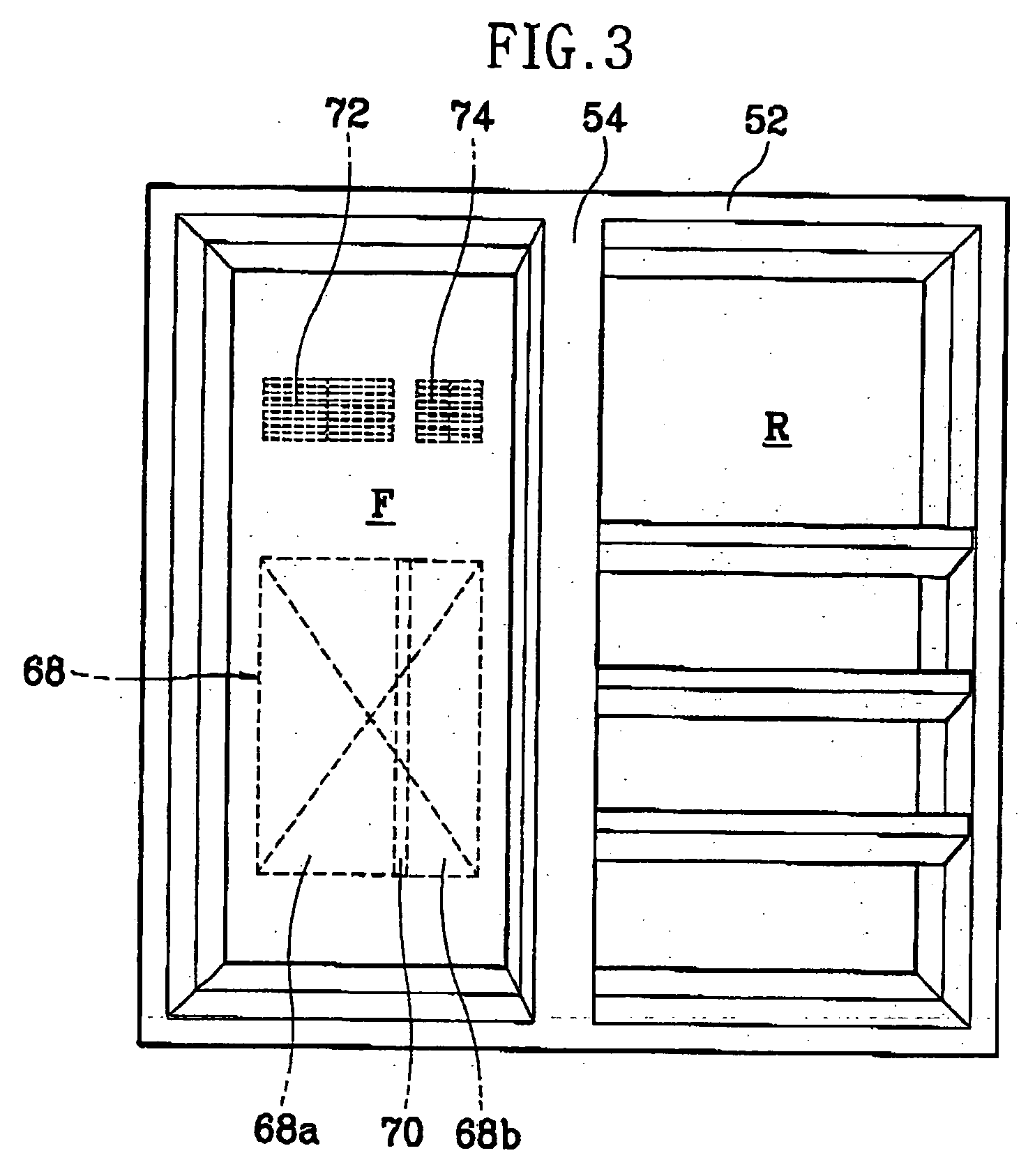
[0038]FIG. 3 is a front perspective view illustrating a side-by-side type refrigerator in accordance with the present invention, and FIG. 4 is a cross-sectional view illustrating the refrigerator of FIG. 3.

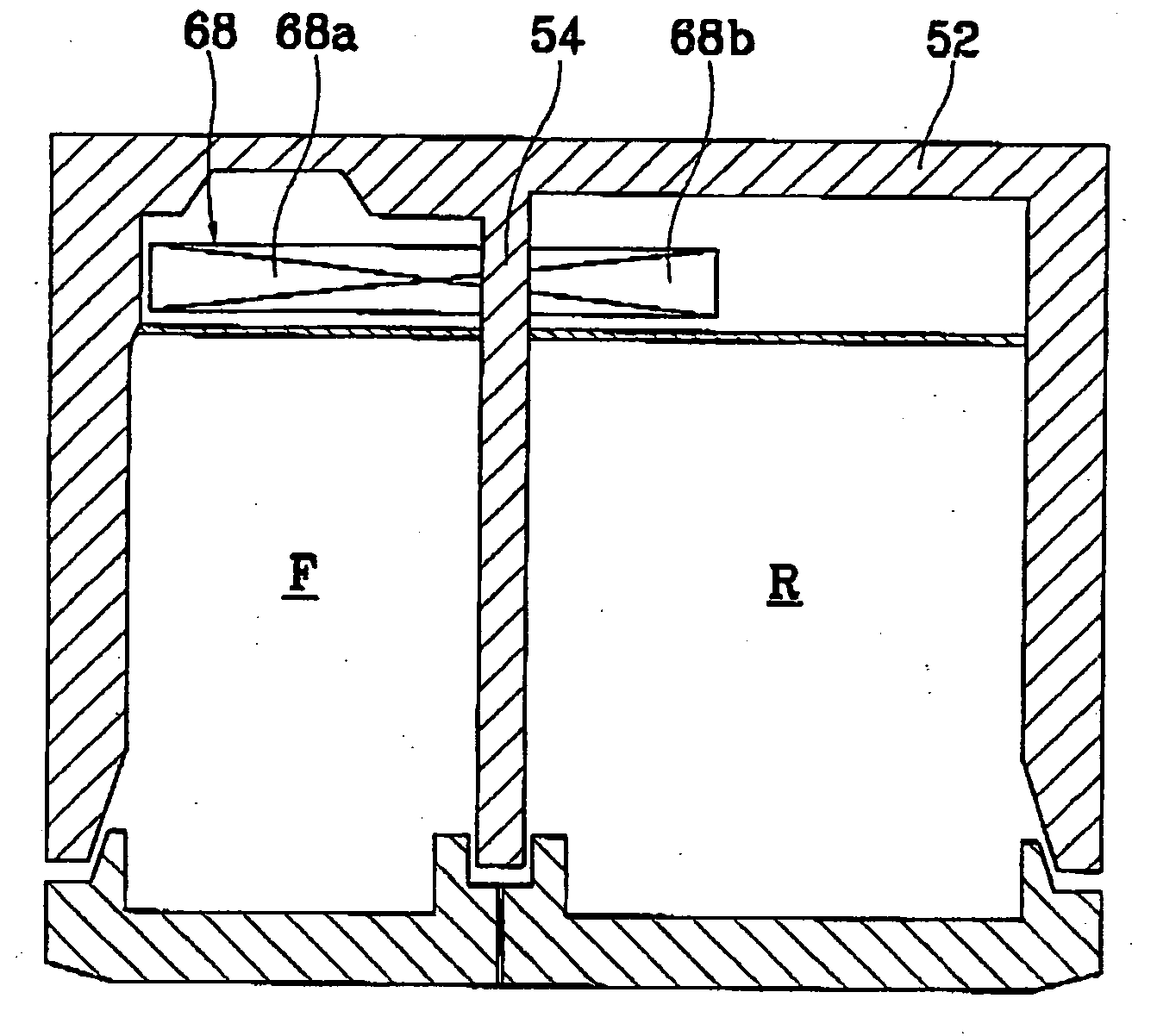
[0039] The refrigerator in accordance with the first embodiment of the present invention will now be described with reference to FIGS. 3 and 4. A freezing chamber F and a refrigerating chamber R are disposed side by side at both sides of a main body 52 from a cross wall 54. A compressor (not shown), a condenser (not shown) and an expansion means (not shown) are built in a machine room (not shown) formed at one side of the freezing chamber F and the refrigerating chamber R. An evaporator 68 is built in the freezing chamber F, for generating cool air by performing a heat exchange operation with refrigerants.

[0040] Especially, the evaporator 68 is divided into a freezing chamber side region 68a and a refrigerating chamber side region 68b. Individual circulation passages are formed t...

second embodiment

[0056]FIG. 5 is a front perspective view illustrating a side-by-side type refrigerator in accordance with the present invention, and FIG. 6 is a cross-sectional view illustrating the refrigerator of FIG. 5.

[0057] The refrigerator in accordance with the second embodiment of the present invention will now be explained with reference to FIGS. 5 and 6. Identically to the first embodiment, a freezing chamber F and a refrigerating chamber R are disposed side by side at both sides of a main body 52 from a cross wall 54. A compressor (not shown), a condenser (not shown) and an expansion means (not shown) are built in a machine room (not shown) formed at one side of the freezing chamber F and the refrigerating chamber R. An evaporator 68 is built in the freezing chamber F and the refrigerating chamber R for generating cool air by performing a heat exchange operation with refrigerants.

[0058] Especially, the evaporator 68 is divided into a freezing chamber side region 68a and a refrigerating ...


PUM


Abstract

The present invention discloses a refrigerator which can individually cool a freezing chamber and a refrigerating chamber by dividing a heat exchange region of an evaporator into a freezing chamber side region and a refrigerating chamber side region, forming individual circulation passages for supplying cool air from each region to the freezing chamber and the refrigerating chamber, and forming a freezing chamber fan and a refrigerating chamber fan on each circulation passage, and method for controlling operation of the same which can efficiently perform a cooling operation and reduce power consumption by effectively controlling the operations of each component.

Description

TECHNICAL FIELD [0001] The present invention relates to a refrigerator which can efficiently perform a cooling operation and reduce power consumption, by individually cooling a freezing chamber and a refrigerating chamber and effectively controlling the operations of each component, and a method for controlling an operation of the same. BACKGROUND ART [0002] In general, a refrigerator is one of the living necessaries which preserves food fresh for a predetermined period, by lowering a temperature of a freezing chamber or a refrigerating chamber by repeating a refrigeration cycle of compressing, condensing, expanding and evaporating refrigerants. [0003] The refrigerator has a refrigeration cycle including basic components such as a compressor for compressing refrigerants into high temperature high pressure gas refrigerants, a condenser for condensing the refrigerants from the compressor into high temperature high pressure liquid refrigerants, an expansion valve for decompressing the ...

Claims


Application Information

Patent Timeline
IPC IPC(8): F25B39/02F25D11/02F25D17/04F25D17/06F25D21/08F25D29/00
CPCF25B39/022F25B2341/066F25B2400/052F25B2500/01F25B2600/2511F25D11/02F25D2700/122F25D21/08F25D29/00F25D2317/0683F25D2400/06F25D2700/12F25D17/065Y10T137/7737F25B41/385F25B41/39
Inventor SIM, JAE-SENGKO, YOUNG-HWANSHIN, JONGMINCHOI, BONG-JUNHWANG, JUN-HYEONJEONG, YOUNGHA, SAMCHULHWANG, YUNHO
Owner LG ELECTRONICS INC
Why Eureka
Try Eureka