Flowmeter mounted on a containment

a technology of flowmeter and containment, applied in the field of flowmeter, can solve problems such as possible readjustments, and achieve the effect of reliable and simple solution

Inactive Publication Date: 2008-12-30
ENDRESS HAUSER FLOWTEC AG
View PDF4 Cites 40 Cited by
  • Summary
  • Abstract
  • Description
  • Claims
  • Application Information

AI Technical Summary

Benefits of technology

[0021]For this problem, an embodiment of the device of the invention provides a very reliable and simple solution: On the basis of the travel time of the measuring signals, which propagate in, and against, the stream direction on at least two different sonic paths in the containment through which the medium is flowing, the control / evaluation unit calculates at least one of the system- or process parameters which is necessary for determining the volume flow of the medium in the containment.

Problems solved by technology

Furthermore, possible readjustments, which, up to now, were required in the case of known solutions as soon as process- or system changes occur, are unnecessary.

Method used


Image

  • Flowmeter mounted on a containment
  • Flowmeter mounted on a containment
  • Flowmeter mounted on a containment

Examples


Embodiment Construction

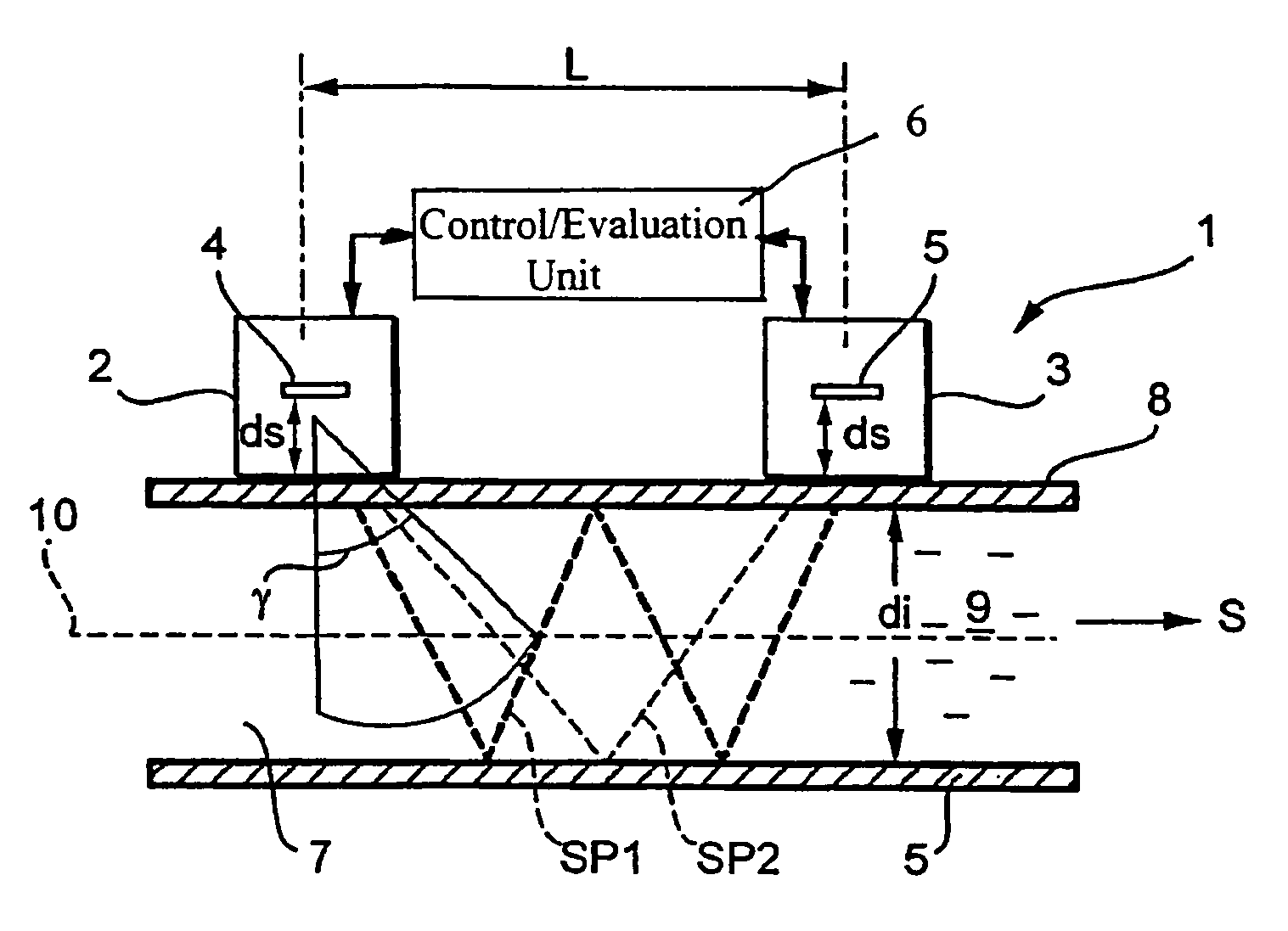
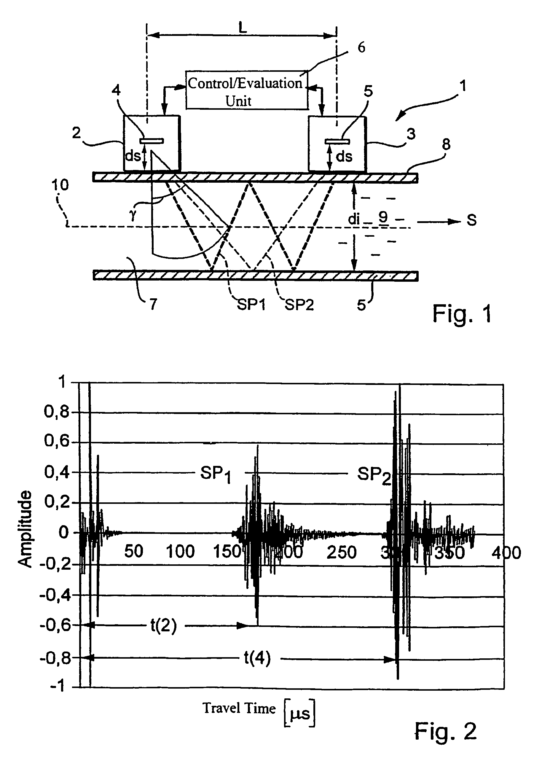
[0025]FIG. 1 is a schematic illustration of a preferred form of embodiment of the ultrasonic flowmeter 1 of the invention. The flowmeter 1 in the illustrated case is a clamp-on flowmeter. The flowmeter 1 determines volume flow rate of the medium 9 in the pipe 7 basically according to the known travel-time-difference method.

[0026]Significant components of the clamp-on ultrasonic flowmeter 1 are the two ultrasonic transducers 2, 3 and the control / evaluation unit 6. The two ultrasonic transducers 2, 3 are attached to the pipe 7 by means of a mounting apparatus (not illustrated separately in FIG. 1). Appropriate mounting apparatuses are sufficiently known from the state of the art, and are also available from the assignee. The medium 9 flows through the pipe 7 of internal diameter di in the stream direction S.

[0027]An ultrasonic transducer 2, 3 has, as significant components, at least one piezoelectric element 4, 5, which produces and / or receives the ultrasonic measuring signals, and a ...


PUM


Abstract

Flowmeter comprising at least two ultrasonic transducers that are mounted on a container which is penetrated by a medium in a certain direction of flow. The ultrasonic transducers alternately transmit and receive ultrasonic test signals in the direction of flow and counter to the direction of flow. The flowmeter further comprises a control/evaluation unit which determines and/or monitors the volume flow of the medium inside the container based on the difference in the travel time of the ultrasonic test signals propagating in the direction of flow and counter to the direction of flow. The ultrasonic transducers are configured such that they transmit and receive ultrasonic test signals or sound fields having a large aperture angle or a great beam expansion.

Description

FIELD OF THE INVENTION[0001]The invention relates to a flowmeter having at least two ultrasonic transducers and a control / evaluation unit. The ultrasonic transducers are mounted on a containment, through which a medium is flowing in a certain stream direction. Based on the difference in the travel time of the measuring signals, which propagate in, and against, the stream direction of the medium, the control / evaluation unit determines the volume flow rate of the medium in the container.BACKGROUND OF THE INVENTION[0002]Ultrasonic flowmeters of the type described above, which determine the volume flow rate on the basis of the so-called travel time method, are used in many cases in process- and automation-technology. These flowmeters permit the volume flow rate in a containment, e.g. in a pipeline, to be measured contactlessly.[0003]There is a differentiation between ultrasonic flow rate sensors, which are inserted into the pipeline, and clamp-on flowmeters, in which the ultrasonic tran...

Claims


Application Information

Patent Timeline
Patent Type & Authority Patents(United States)
IPC IPC(8): G01F1/66
CPCG01F1/66
Inventor FROEHLICH, THOMASWIEST, ACHIMSTRUNZ, TORSTEN
Owner ENDRESS HAUSER FLOWTEC AG
Why Eureka
Try Eureka