Permanently lubricated film gasket and method of manufacture

a film gasket and permanent lubrication technology, applied in the field of elastomeric gaskets, can solve the problems of large frictional force, fluid leakage, ground water leakage, etc., and achieve the effect of reducing the potential for failure and minimizing the potential for tearing or cutting in the material

Inactive Publication Date: 2008-12-30
SPRINGSEAL
View PDF91 Cites 32 Cited by
  • Summary
  • Abstract
  • Description
  • Claims
  • Application Information

AI Technical Summary

Benefits of technology

[0015]In another embodiment, the second portion and the permanently lubricating chemical film are joined at a die head or through an injection mold process. Such approach eliminates the need for any labor and cost intense secondary operation.
[0017]Another feature is that in most applications the lubricating film forms a protective shell over the gasket minimizing the potential for tearing or cuts in the material. Yet another feature of the lubricating film is the ability to integrate the film to controlled areas along the leading edge of the second portion, thereby allowing a trailing portion of the second portion to lock or grip the pipe when forces are applied opposite the direction of the lubricating film.
[0018]Another feature is the controlled placement and static characteristics of the lubricating film, which substantially reduces the potential for failure when performing welding and joining operations to the ends of the gasket.

Problems solved by technology

Typically, a large frictional force is encountered when the inner pipe and the elastomeric gasket is inserted into the outer pipe.
When the pipe is not properly sealed, ground water may leak into the pipe or fluid may leak out of the pipe and contaminate the ground.
The manual application of the lubricant is labor intensive and is usually performed in a trench or ditch making the lubricant susceptible to being removed by water frequently found in such environments.
In addition, the spray operations lack the ability to control the thickness of the lubricant coatings and the coatings often crack inhibiting the gaskets ability to stretch or compress without resulting in seal failure.
The migration results in an oily texture on the surface of the gasket that can be undesirable in certain applications.
A migrating lubricant agent produces an oily texture on the gasket surface that attracts dust and debris, which can lead to leaks and failure in the pipe joint when assembled.
There also exists a problem of chemical migration to areas undesirable of lubrication.

Method used


Image

  • Permanently lubricated film gasket and method of manufacture
  • Permanently lubricated film gasket and method of manufacture
  • Permanently lubricated film gasket and method of manufacture

Examples


Embodiment Construction

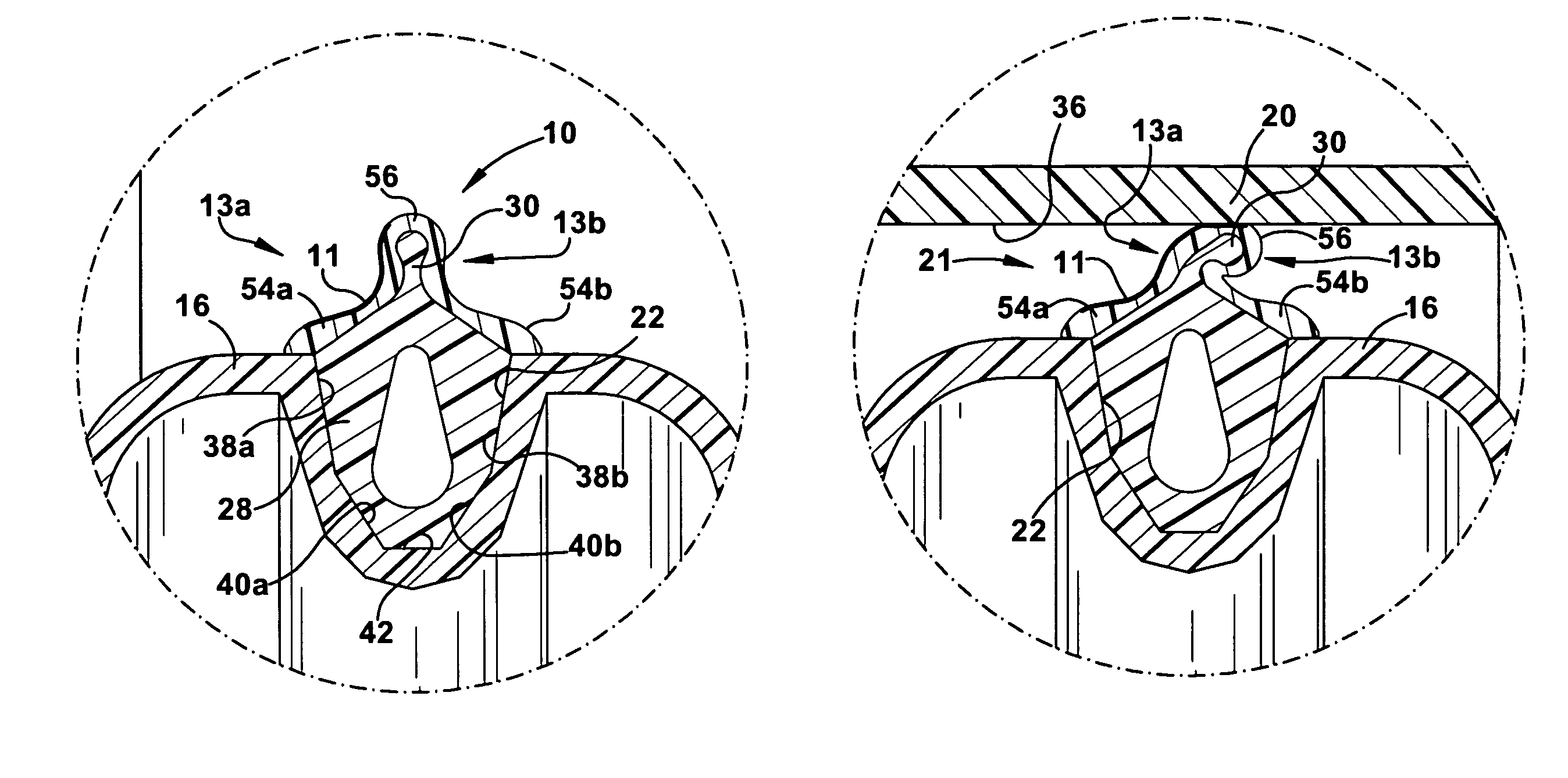
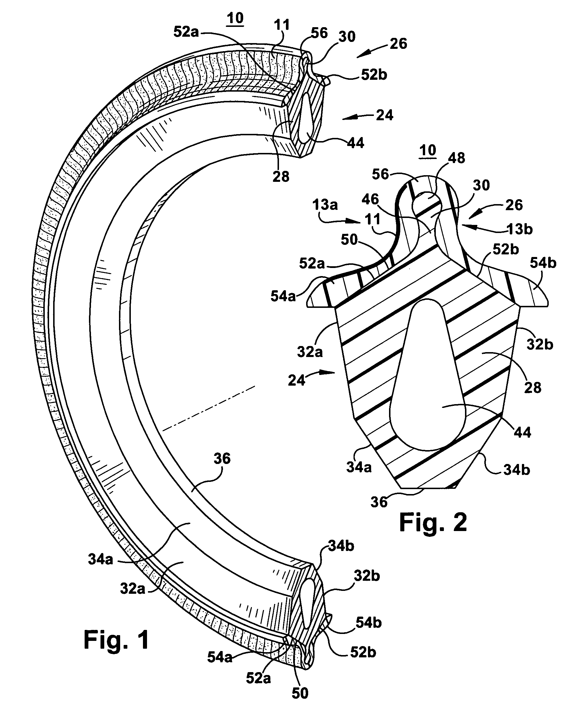
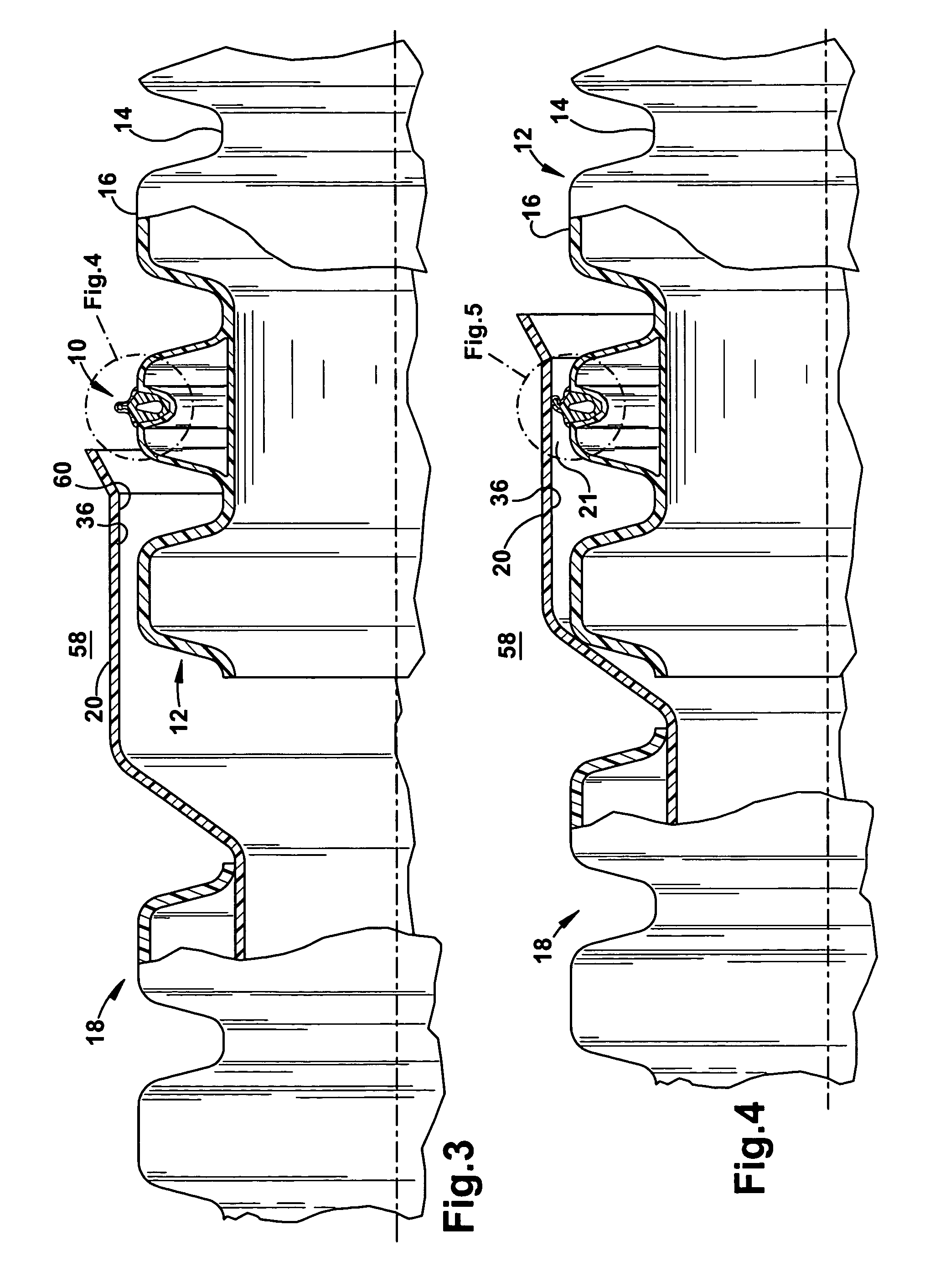
[0028]The present invention is directed to a permanently lubricated film annular gasket 10, depicted in FIGS. 1 and 2, for providing a fluid tight seal between a first tubular member 12 and second tubular member 18, as shown in FIGS. 3 and 4. In the illustrated embodiment, the first tubular member has a plurality of annular grooves 14 and ridges 16 and the second tubular member includes a smooth annular section 20, such as a bell.

[0029]Referring again to FIGS. 1 and 2, the annular gasket 10 includes a first, support portion 24 and a second, elastomeric gasket portion 26. The support portion 24 is made from a material having a first, relatively hard, durometer. The elastomeric gasket portion 26 is made from a relatively soft, durometer material, and includes a leading edge 13a and oppositely positioned trailing edge 13b. Formed along a substantial portion of the leading edge 13a of gasket portion 26 is a permanently lubricated film 11. The permanently lubricated film could be made fr...


PUM


Abstract

A permanently lubricated film gasket for providing a fluid-tight seal between a corrugated pipe and a smooth annular section of an outer pipe or section when the corrugated pipe and the outer pipe or section are in a relative surrounded and surrounding relationship. A first portion of the gasket is shaped to fit within a groove or recess of the corrugated pipe. A second portion of the gasket extends from the first portion. The second portion is at least partially comprised of permanently lubricated film for facilitating in the connection of the pipes along a single direction.

Description

CROSS-REFERENCES TO RELATED APPLICATIONS[0001]The present application is a continuation-in-part application containing common subject matter as previously filed and application Ser. No. 10 / 419,541, filed in the U.S. Patent and Trademark Office on Apr. 21, 2003 now abandoned, entitled “PERMANENTLY LUBRICATED GASKET”, which is a continuation-in-part of U.S. application Ser. No. 09 / 998,697, filed in the U.S. Patent and Trademark Office on Nov. 30, 2001, to issue as U.S. Pat. No. 6,550,775, entitled “ANNULAR GASKET,” which is a continuation-in-part of U.S. patent application Ser. No. 09 / 726,814 filed in the U.S. Patent and Trademark Office on Nov. 30, 2000, entitled “ANNULAR GASKET WITH LOCKING STRUCTURE,” now U.S. Pat. No. 6,367,802. The present application claims priority the aforementioned patents and patent applications, which are incorporated in their entirety herein by reference for all purposes.TECHNICAL FIELD[0002]The present invention relates to elastomeric gaskets for providin...

Claims


Application Information

Patent Timeline
Patent Type & Authority Patents(United States)
IPC IPC(8): F16L21/02F16L17/025F16L17/06
CPCF16L17/025F16L21/035F16L25/0054F16J15/027F16L25/0036Y10S285/903
Inventor KNAPP, MARK
Owner SPRINGSEAL
Why Eureka
Try Eureka