
Apparatus and method for forming a container having an enhanced corner support structure

a technology of corner support structure and container, applied in the field of container fabrication system, can solve the problems of negative effect of increased stroke on cycle time, and achieve the effect of reducing cycle time, increasing tray height, and efficient housing

Active Publication Date: 2008-12-30
WESTROCK SHARED SERVICES LLC
View PDF27 Cites 46 Cited by
  • Summary
  • Abstract
  • Description
  • Claims
  • Application Information

AI Technical Summary

Benefits of technology

[0006]By modifying the above apparatus to include a powered folding inside corner support member (also herein referred to as an end flap), an improved embodiment efficiently accommodates the forming of generally deep containers or trays. Improvements to the tray forming apparatus may include a power folding end flap mechanism, a power folding end panel mechanism, and an end flap device for controlling glue portions of the blank, which blank is fed into a forming area of the apparatus horizontally and flat.
[0008]Powering the movement of the end flaps and end panel, beyond simply allowing the platen to move the blank past fixed folding elements improves on the efficiency of the apparatus and permits the forming of relatively deep trays or containers, as will further detailed later in this specification. A design problem typically faced by those skilled in the art is how to get the paperboard blank into the forming area without impacting on the position of the flaps as it was being folded. Flaps must be folded in order of the process or a lock out of the flaps will occur. This is easily realized when one tries to fold the side panel and end flaps at the same time. The power folding features of the embodiment herein described by way of example solves this problem as the folding occurs upward before the side panels are moved. By way of further example, this removes restrictions of having a rail to (deliver the blank) in the folding area.

Problems solved by technology

This increased stroke has a negative effect on the cycle time.
A design problem typically faced by those skilled in the art is how to get the paperboard blank into the forming area without impacting on the position of the flaps as it was being folded.

Method used


Image

  • Apparatus and method for forming a container having an enhanced corner support structure
  • Apparatus and method for forming a container having an enhanced corner support structure
  • Apparatus and method for forming a container having an enhanced corner support structure

Examples


Embodiment Construction

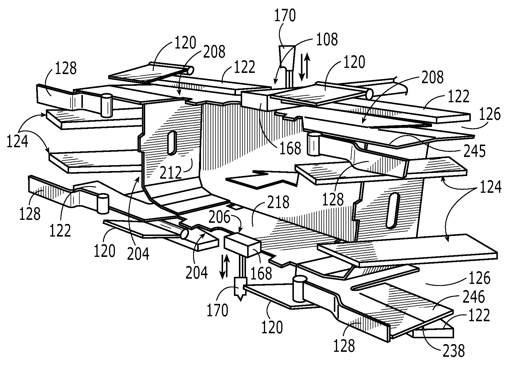
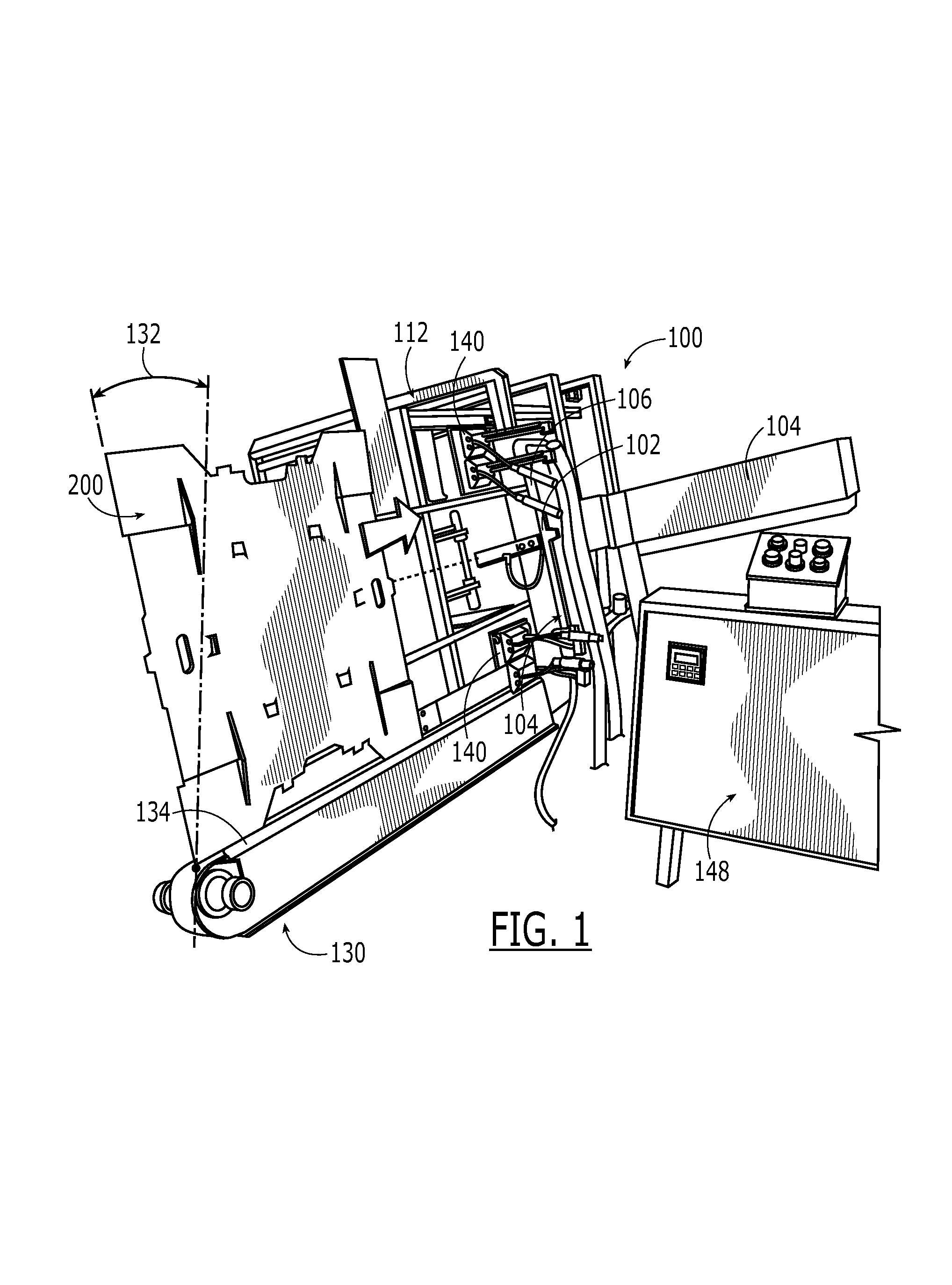
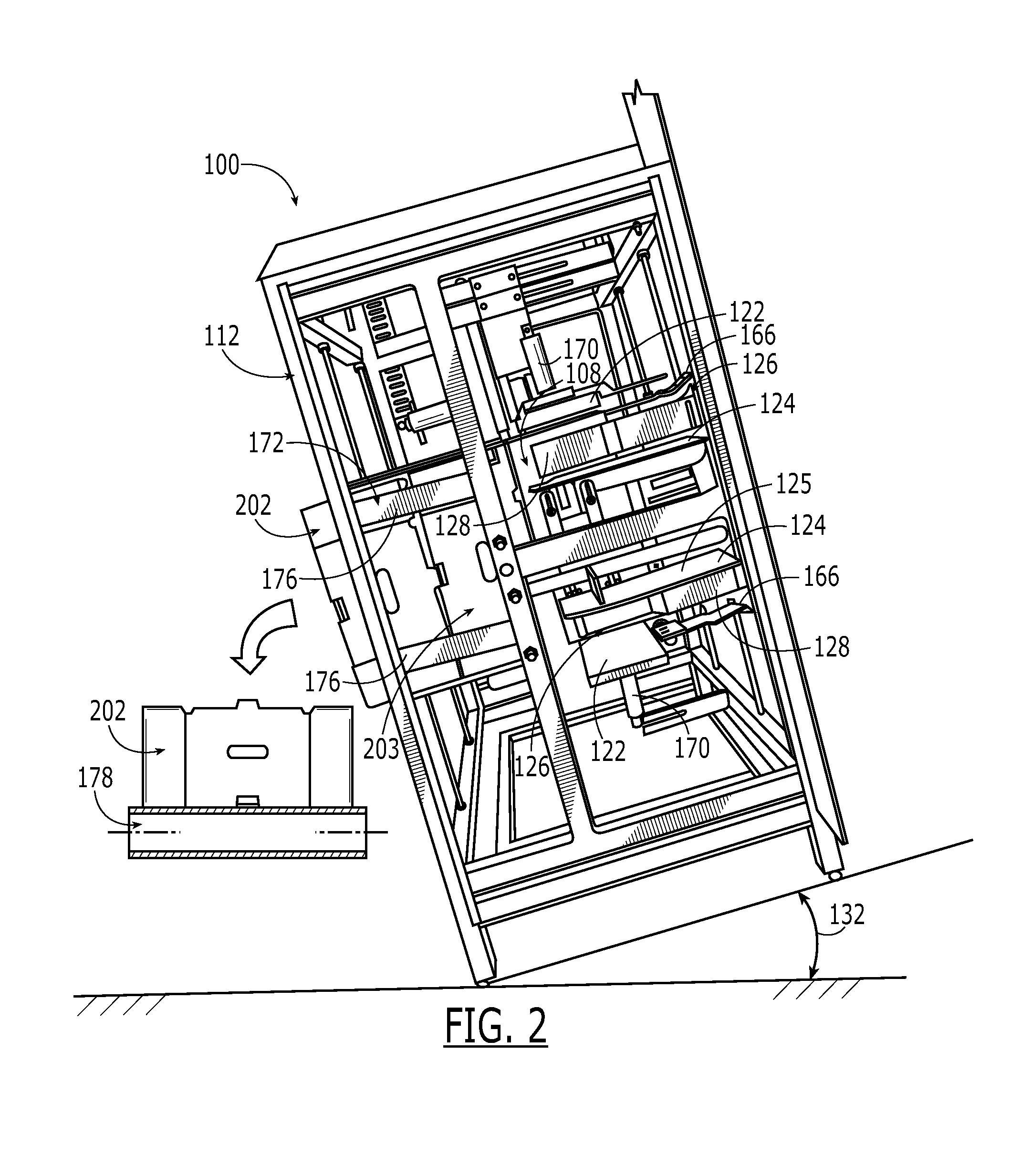
[0038]The present invention will now be described more fully hereinafter with reference to the accompanying drawings, in which embodiments of the invention are shown. This invention may, however, be embodied in many different forms and should not be construed as limited to the embodiments set forth herein. Rather, the embodiments herein presented are provided so that this disclosure will be thorough and complete, and will fully convey the scope of the invention to those skilled in the art. By way of example, and with reference initially to FIGS. 1 and 2, one embodiment of the present invention includes a tray forming apparatus 100 for forming a blank 200 into a fully formed tray 202. The apparatus 100 may further be described to include a platen 102 dimensioned for biasing against the blank 200 using a platen drive 104 operable for moving the platen between a first position 104 proximate and in spaced relation to the blank 200 and a second position 108, illustrated with reference ag...


PUM


Abstract

An apparatus automatically forms a paperboard blank into a container having a double glued side wall construction for providing an enhanced strength to the container. A platen drives the blank through mechanically powered forming rails for an initial folding of the blank into a partially formed container having a bottom, end and side walls, and inside corner supports. A compression plate and folding arms are biased against adhesive portions of the partially formed container for forming a fully formed container having a double glued side wall construction.

Description

CROSS REFERENCE TO RELATED APPLICATIONS[0001]This application incorporates by reference and claims priority to application Ser. No. 60 / 711,277 FOR “Horizontal Feed Tray Forming Apparatus” having filing date Aug. 25, 2005 and to application Ser. No. 10 / 721,962 filed Nov. 25, 2003 for “Apparatus and Method for Forming a Double Glued Corner Tray Structure” which itself claims priority to application Ser. No. 60 / 429,319 filed Nov. 26, 2002 for “Tray Forming Apparatus And Method Of Forming A Double Glued Corner Tray Structure,” all being commonly owned.FIELD OF INVENTION[0002]The present invention generally relates to container fabrication systems, and in particular to a container forming apparatus and automated method of forming a container from a scored paperboard blank, the container having a reinforced corner construction.BACKGROUND OF THE INVENTION[0003]It is well known in the art to use paperboard trays for stacking during delivery to a final destination such as a grocery store and...

Claims


Application Information

Patent Timeline
IPC IPC(8): B31B1/48B31B50/44B31B50/46B31B50/48B31B50/52B31B50/62
CPCB65D5/0045B31B1/26B31B1/00B31B2201/2666B31B2201/267B31B2201/28B31B2201/283B31B2201/6091B31B2203/003B31B2203/084B31B50/46B31B50/52B31B50/732B31B50/76B31B50/784B31B2100/00B31B2100/0024B31B2120/30B31B50/26B31B50/44
Inventor HERRIN, ROBERT M
Owner WESTROCK SHARED SERVICES LLC
Features
  • Generate Ideas
  • Intellectual Property
  • Life Sciences
  • Materials
  • Tech Scout
  • Unparalleled Data Quality
  • Higher Quality Content
  • 60% Fewer Hallucinations
Learn More