Battery and battery manufacturing method

a battery and manufacturing method technology, applied in the field of batteries, can solve the problems of difficult method for forming the welding portion as such, and achieve the effect of excellent battery performan

Active Publication Date: 2008-12-30
THE FURUKAWA BATERY CO LTD
View PDF9 Cites 6 Cited by
  • Summary
  • Abstract
  • Description
  • Claims
  • Application Information

AI Technical Summary

Benefits of technology

[0010]The object of the present invention is therefore to provide a battery that prevents growth of cracks in the welding portion of the outer package can and the power collecting body to prevent leakage of electrolyte through the cracks so as to maintain an excellent battery performance, and a method of manufacturing the battery.
[0012]The welding portion in the above-stated battery of the present invention is formed by first forming a welding portion, which corresponds to the first layer, having relatively large crystal grains by performing a normal laser welding, and then forming the second layer (reinforcement layer) having minuter crystal grains. With this construction, if a crack occurs in the first layer (weak layer) of the welding portion, growth of the crack is blocked by the reinforcement layer. This provides an effect of preventing the electrolyte from leaking. Accordingly, it is expected that the battery of the present invention maintains the excellent battery performance even if it is used in such conditions that would allow cracks to grow in a conventional battery, for example, in such conditions that require a large amount of current for charges and discharges.
[0013]It should be noted here that although one might think that the whole welding portion may be a reinforcement layer such as the second layer, the method for forming the welding portion as such is considered to be difficult. In contrast, the present invention makes full use of the normal welding method, avoiding a drastic change of the welding method. As a result, the present invention provides a relatively easy method for achieving such an excellent advantageous effect.

Problems solved by technology

It should be noted here that although one might think that the whole welding portion may be a reinforcement layer such as the second layer, the method for forming the welding portion as such is considered to be difficult.

Method used


Image

  • Battery and battery manufacturing method
  • Battery and battery manufacturing method
  • Battery and battery manufacturing method

Examples


embodiment

1-1. Construction of Alkaline Storage Battery

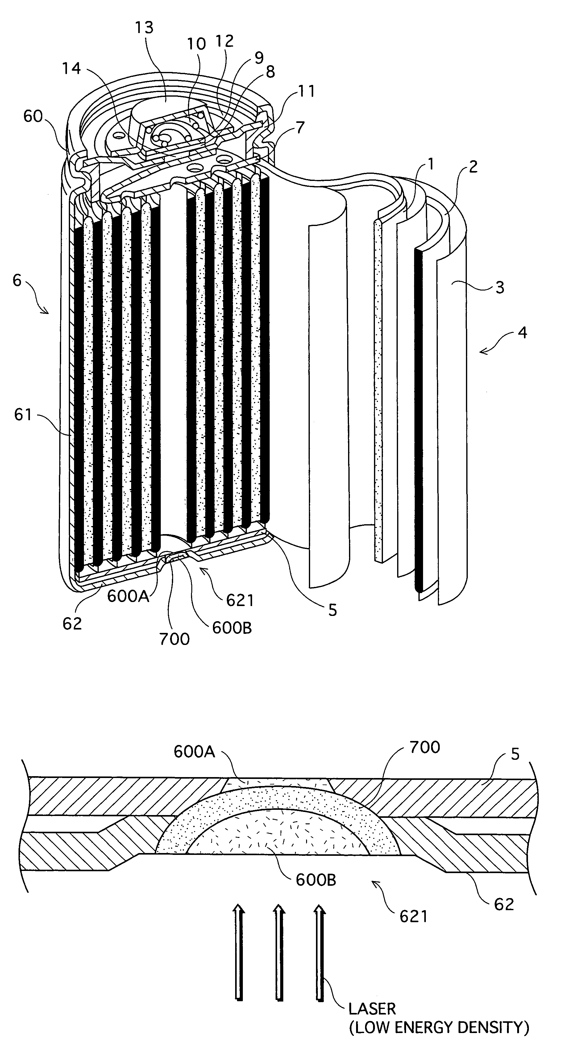
[0023]FIG. 1 is a sectional perspective view of a cylindrical nickel-cadmium (Ni—Cd) storage battery of the present invention.

[0024]The storage battery includes a cylindrical outer package can 6 of an SC size in which a bundle of electrodes and separator 4, electrolyte and the like are housed. The nominal capacitance may be, for example, 2.4 Ah. Alkaline solution is used as the electrolyte. In the present embodiment, a potassium-hydroxide-based solution is used as one example.

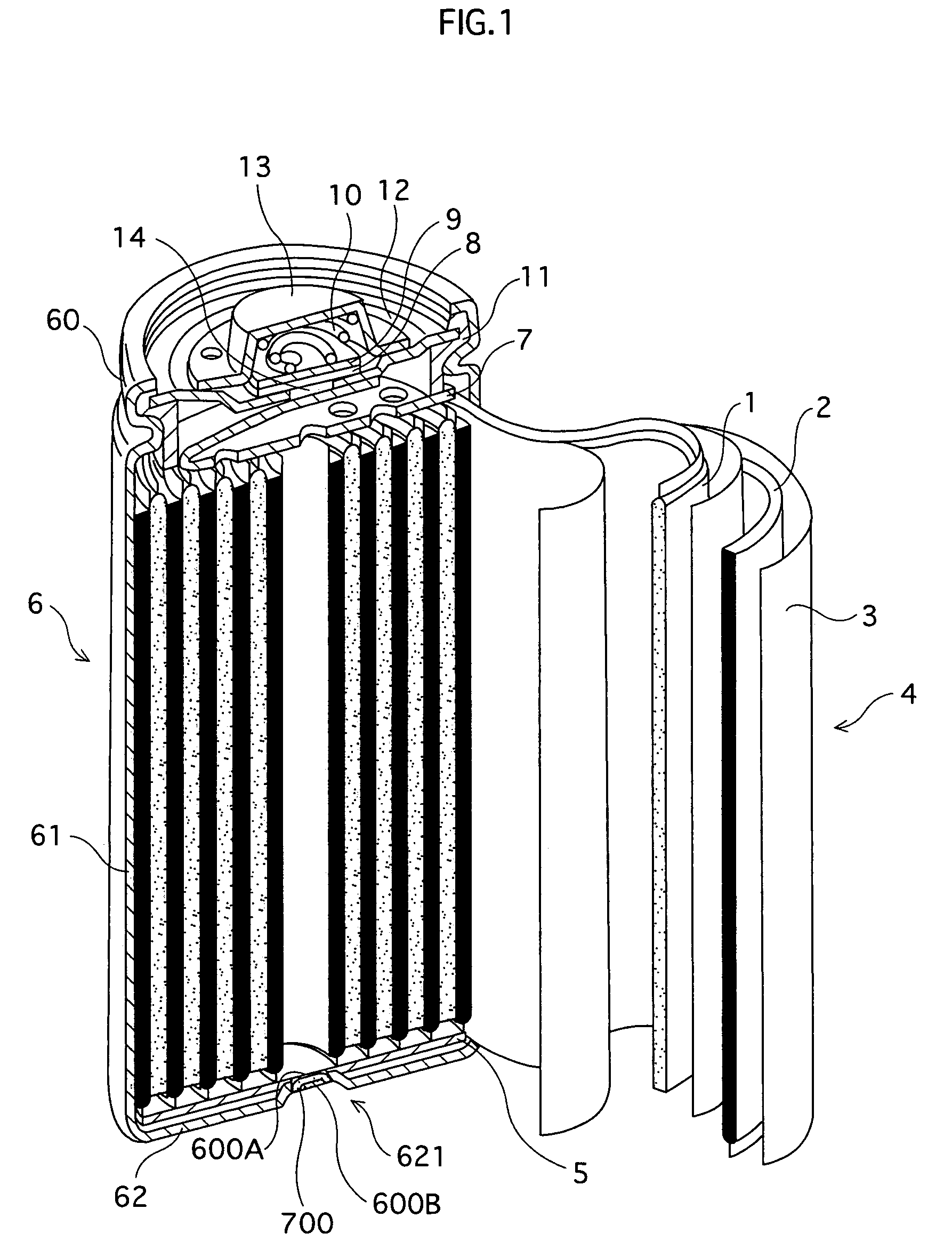
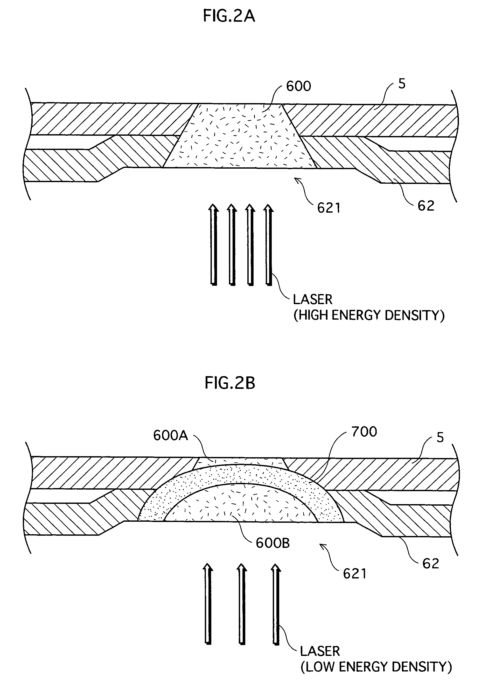
[0025]The cylindrical outer package can 6 is made by forming Ni-coated Fe into a cylinder with a bottom. Other metal materials such as a stainless material and aluminum may be used depending on the type or characteristics of the battery. A side surface 61 of the cylindrical outer package can 6 is coated with a resin film or a material for isolating the can from outside. A bottom 62 of the cylindrical outer package can 6 has an inward dent 621 approximately at a cente...


PUM

PropertyMeasurementUnit
thicknessaaaaaaaaaa
shapeaaaaaaaaaa
energy densityaaaaaaaaaa

Abstract

A battery having a bundle of electrodes and separator which is made by winding a positive-electrode plate and a negative-electrode plate together with a separator therebetween, one of the positive- and negative-electrode plates being electrically connected to a power collecting body, the power collecting body being provided in and welded to an outer package can, wherein a welding portion of the outer package can and the power collecting body comprises a first layer and a second layer which are stacked in a thickness direction of the outer package can at the welding portion, and the second layer is in contact with a surface of the first layer and includes crystal grains that are minuter than crystal grains included in the first layer.

Description

BACKGROUND OF THE INVENTION[0001](1 )Field of the Invention[0002]The present invention relates to a battery that is manufactured using energy beams, and to a manufacturing method of the battery.[0003](2) Description of the Related Art[0004]Energy beam welding is widely used for manufacturing batteries housed in metal outer package cans, as disclosed in Japanese Laid-Open Patent Applications H4-162351, H8-293299, and 2000-77040 and Japanese Patent Publication No. H2-15985.[0005]A cylinder alkaline storage battery, for example, is manufactured as follows. First, a bundle of electrodes and separator is made by winding a positive-electrode plate and a negative-electrode plate together with a separator between them. The positive-electrode plate and negative-electrode plate of the bundle are welded to the positive- and negative-electrode power collecting bodies, respectively. Then the bundle is housed in a metal outer package can. The positive-electrode power collecting body is connected ...

Claims


Application Information

Patent Timeline
Patent Type & Authority Patents(United States)
IPC IPC(8): H01M2/02B23K26/00H01M10/04H01M10/24H01M50/528
CPCH01M2/023H01M10/0431Y10T29/49114H01M10/24Y02E60/10H01M50/56Y02P70/50
Inventor TOMIMOTO, KAZUOSHIMOZONO, KAZUKIFUJISAKA, ETSUYANAKANO, FUTOSHIHOSOKAWA, HIROSHI
Owner THE FURUKAWA BATERY CO LTD
Why Eureka
Try Eureka