
Method and apparatus for vascular durability and fatigue testing

a durability and fatigue testing technology, applied in the field of vascular prosthesis testing, can solve the problems of stent-grafts being subjected to varying dynamic mechanical stress, abnormal dilation of the abdominal part of the aorta, and regime limited to fluid pressure-induced stress

Inactive Publication Date: 2009-01-06
TA INSTR WATERS LLC
View PDF10 Cites 30 Cited by
  • Summary
  • Abstract
  • Description
  • Claims
  • Application Information

AI Technical Summary

Benefits of technology

"The present invention provides a vascular prosthesis tester that can induce mechanical stresses on a vascular prosthesis to test its performance. The tester includes a pump to pressurize fluid within the prosthesis to induce a radial strain, a bend applicator to induce a bending stress, a torque applicator to induce a torque, and a linear force applicator to induce a linear force. The tester may also include a stop to limit the perpendicular displacement of the fluid conduit. The method involves inducing a radial stress, torque, bending stress, and linear stress on the vascular prosthesis and its fluid conduit. The technical effects of the invention include providing a reliable and effective tool for testing the performance of vascular prosthesis and ensuring their quality."

Problems solved by technology

An AAA is an abnormal dilation of the abdominal part of the aorta, which is frequently fatal if ruptured.
A testing regime limited to fluid-pressure-induced stresses fails to adequately simulate the physiological stresses exhibited upon a stent-graft, since the physiological stresses exhibited upon an AAA stent-graft are substantially more complex and varied than a stenotic stent.
Furthermore, the geometric features of the vessels change significantly during normal physiologic movements, such as sitting or walking, thereby subjecting the stent-graft to varying dynamic mechanical stress.

Method used


Image

  • Method and apparatus for vascular durability and fatigue testing
  • Method and apparatus for vascular durability and fatigue testing
  • Method and apparatus for vascular durability and fatigue testing

Examples


Embodiment Construction

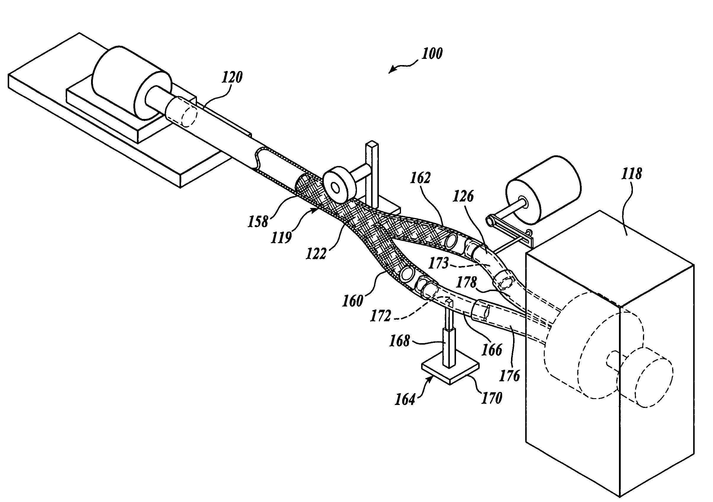
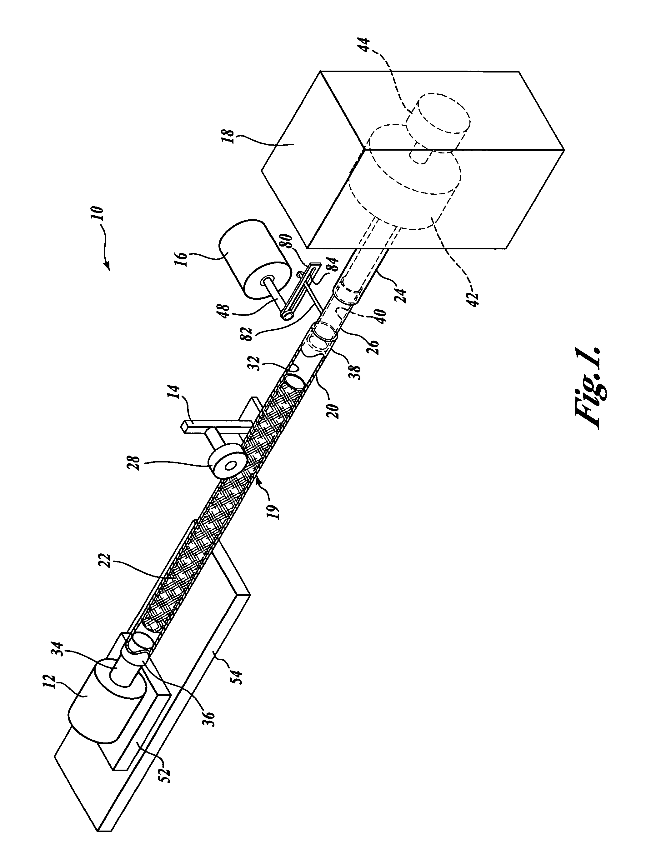
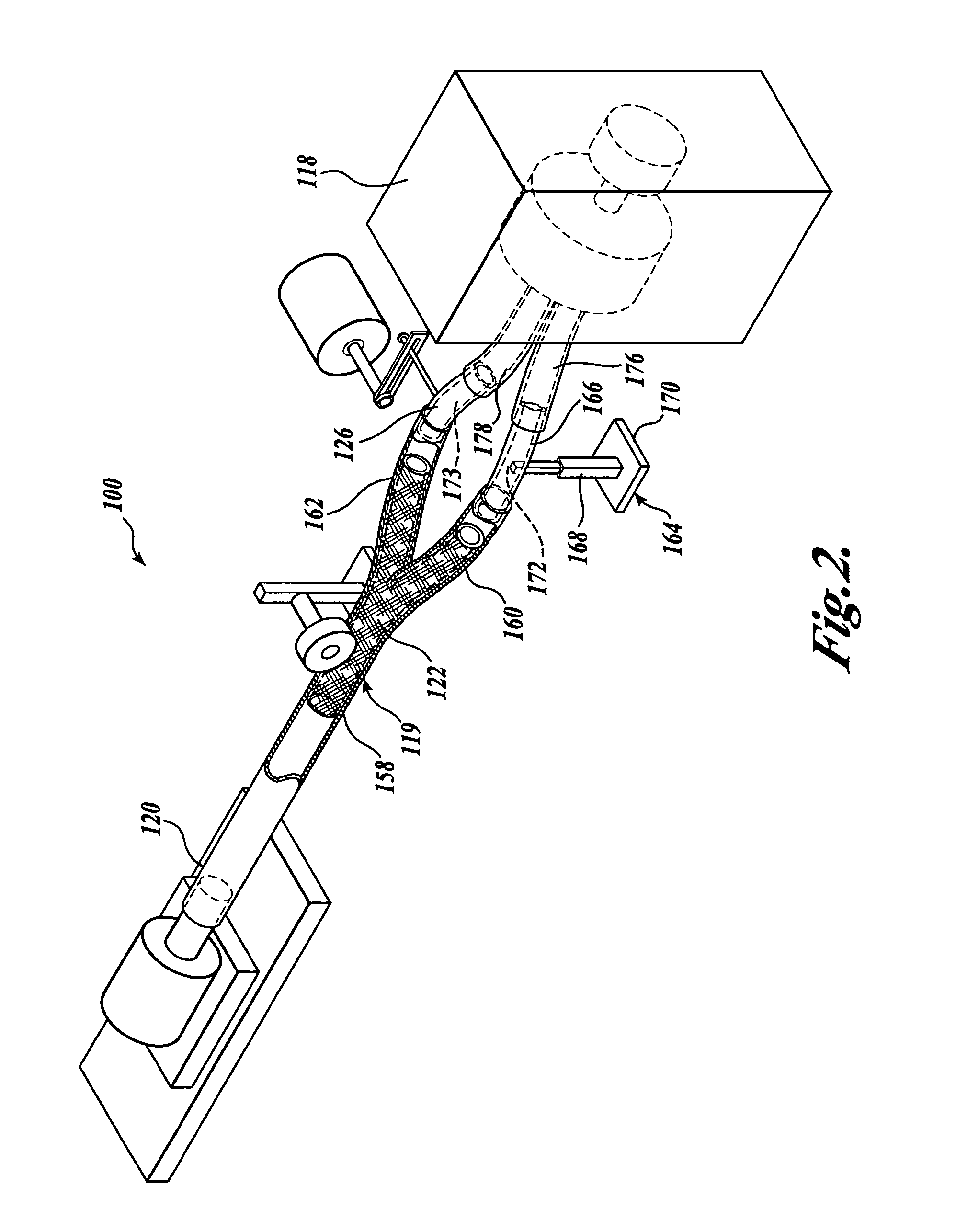
[0017]FIG. 1 illustrates a vascular prosthesis tester 10 formed in accordance with one embodiment of the present invention and suitably used for inducing mechanical stresses upon a vascular prosthesis, such as a stent-graft 22. The illustrated embodiment of the vascular prosthesis tester 10 of the present invention is configured to subject a stent-graft 22 to tensile and / or compressive axial loads, bending stresses, torsional stresses, lateral push stresses, pressure-induced radial strain, and / or fluid shear stresses. The forces may be applied in an oscillatory or gradually varying manner by force applicators or actuators, which may be driven by mechanical, electrical, pneumatic, hydraulic or other suitable means. Further, the actuators may induce the stresses independently or in combination, or in a manner to simulate a physiologic movement, such as walking.

[0018]The forces are applied upon what, for the purposes of this detailed description, will be generally referred to as a test...


PUM

PropertyMeasurementUnit
lengthsaaaaaaaaaa
diameteraaaaaaaaaa
diameteraaaaaaaaaa

Abstract

A vascular prosthesis tester (10) for inducing stresses upon a vascular prosthesis (22) having a channel extending through the vascular prosthesis is disclosed. The tester includes a pump (18) adaptable to pressurize a fluid disposed within the channel to induce a radial stress upon the vascular prosthesis. The tester may further include a bend applicator (16) operable to induce a bending stress, a torque applicator (12) operable to induce a torque, a linear force applicator (52) operable to induce a linear force, and / or a stop (28) for inducing a lateral push stress upon the vascular prosthesis. A method of fatigue testing a vascular prosthesis contained within a fluid conduit is also disclosed. The method includes injecting a fluid within the inner channel and inducing a torque, bending stress, linear stress, and / or later push stress upon the vascular prosthesis.

Description

CROSS-REFERENCE TO RELATED APPLICATION[0001]This application is a continuation of Ser. No. 10 / 208,497, filed Jul. 29, 2002 U.S. Pat. No. 6,810,751, issued Nov. 2, 2004, entitled METHOD AND APPARATUS FOR VASCULAR DURABILITY AND FATIGUE TESTING, the disclosure of which is hereby expressly incorporated by reference and the priority from the filing date of which is hereby claimed under 35 U.S.C. § 120.FIELD OF THE INVENTION[0002]The present invention relates generally to the field of vascular prosthesis testing, and more particularly, to vascular prosthesis testing that simulates physiological loading conditions.BACKGROUND OF THE INVENTION[0003]Vascular prosthesis, such as stents, grafts, and stent-grafts are often used in the medical field to repair vascular abnormalities in a patient. In one such non-limiting example, a vascular prosthesis may be used to repair an Abdominal Aortic Aneurysm (hereinafter “AAA”). An AAA is an abnormal dilation of the abdominal part of the aorta, which is...

Claims


Application Information

Patent Timeline
Patent Type & Authority Patents(United States)
IPC IPC(8): G01N3/20A61F2/02G01N3/32
CPCG01N3/32A61F2240/008G01N2203/0016G01N2203/0021G01N2203/0023
Inventor MOORE, JR., JAMES EMORENO, MICHAEL R
Owner TA INSTR WATERS LLC
Learn More