Assembly of a part that has no plastic domain

a technology of plastic domain and assembly, applied in the field of assembly of parts, can solve the problems of silicon-based parts breaking, parts not binding sufficiently well, and operation requires extremely delicate applications

Active Publication Date: 2012-06-28
NIVAROX FAR
View PDF3 Cites 11 Cited by
  • Summary
  • Abstract
  • Description
  • Claims
  • Application Information

AI Technical Summary

Benefits of technology

[0010]c) elastically and plastically deforming the flared portion of said member in the aperture by moving two tools towards each other axially, respectively on the top and bottom parts of said flared portion, so as to exert a radial stress against the wall of the part surrounding the aperture, causing the elastic deformation of the part, to secure the assembly in a manner that is not destructive for said part.
[0011]This method advantageously allows the member to be radiall

Problems solved by technology

This type of operation requires extremely delicate application which makes it expensive.
However, the embodiments proposed in this document are unsatisfactory and either cause the silicon-based part to break during assembly, or do not bind the parts sufficiently well to each other.
Indeed, in this document, o

Method used


Image

  • Assembly of a part that has no plastic domain
  • Assembly of a part that has no plastic domain
  • Assembly of a part that has no plastic domain

Examples


first embodiment

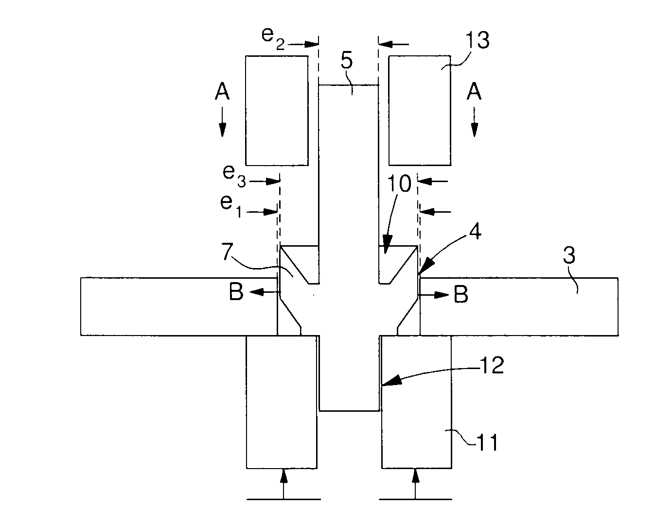
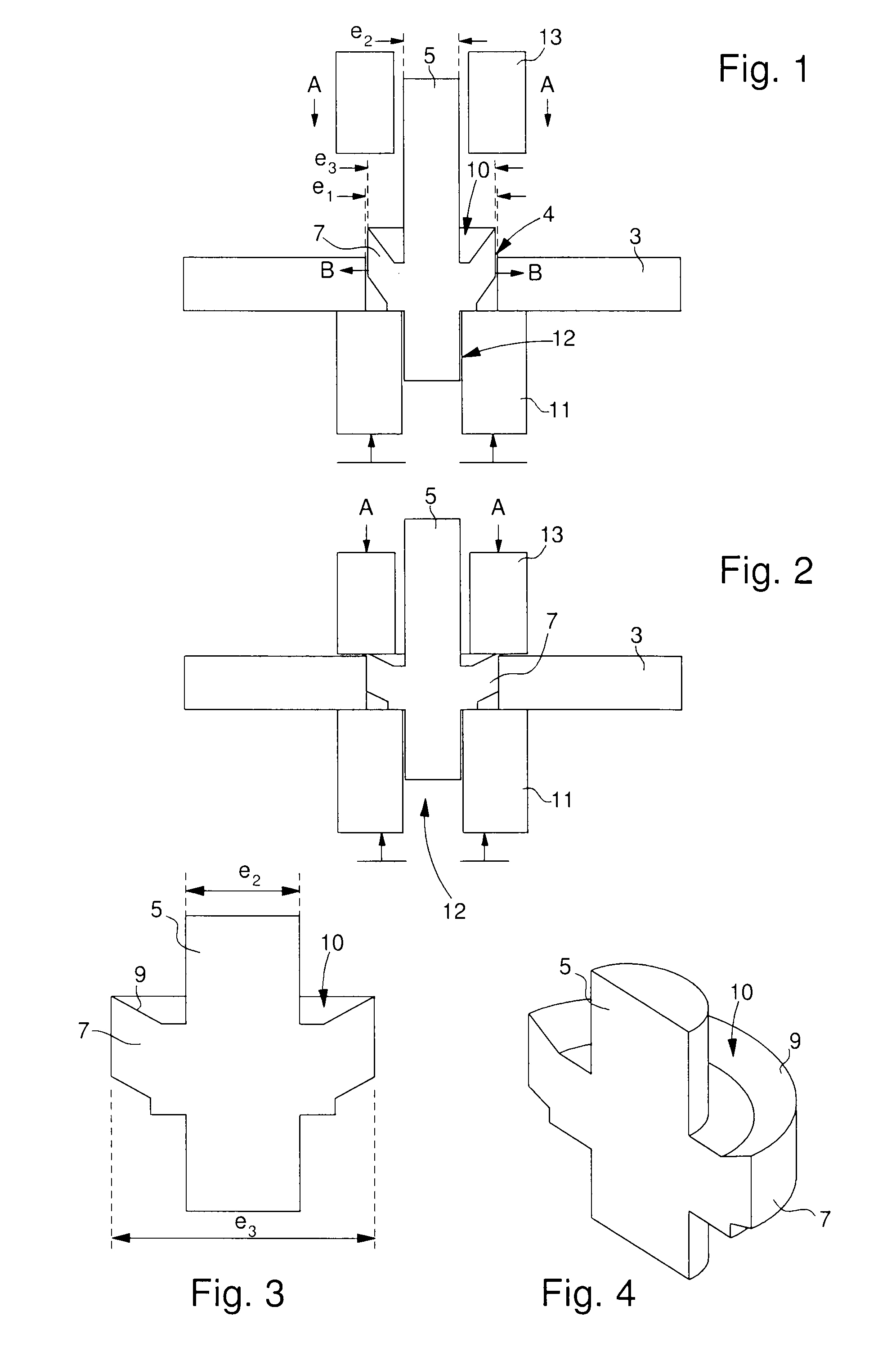
[0048]FIGS. 1 to 4 show a first embodiment according to the invention. A first step thus consists in forming part 3 in a material having no plastic domain and with a circular aperture 4. As shown in FIG. 1, aperture 4 has a section e1, which is preferably comprised between 0.5 and 2 mm and if appropriate, flutes 1 of FIG. 11 projecting into aperture 4 have a height of between 5 and 25 μm.

[0049]This step may be achieved by dry or wet etching, for example DRIE (deep reactive ion etching).

[0050]Further, in a second step, the method consists in forming the member, which is a pivot pin 5 in the example of FIGS. 1 and 2, in a second material with a main section e2 and a radially flared portion 7, which is intended to be deformed, with a maximum section e3. Flared portion 7 may have a thickness of between 100 and 600 μm. As explained hereinbefore, the second step can be carried out in accordance with usual arbour fabrication processes. Member 5 is preferably metal and may for example be fo...

second embodiment

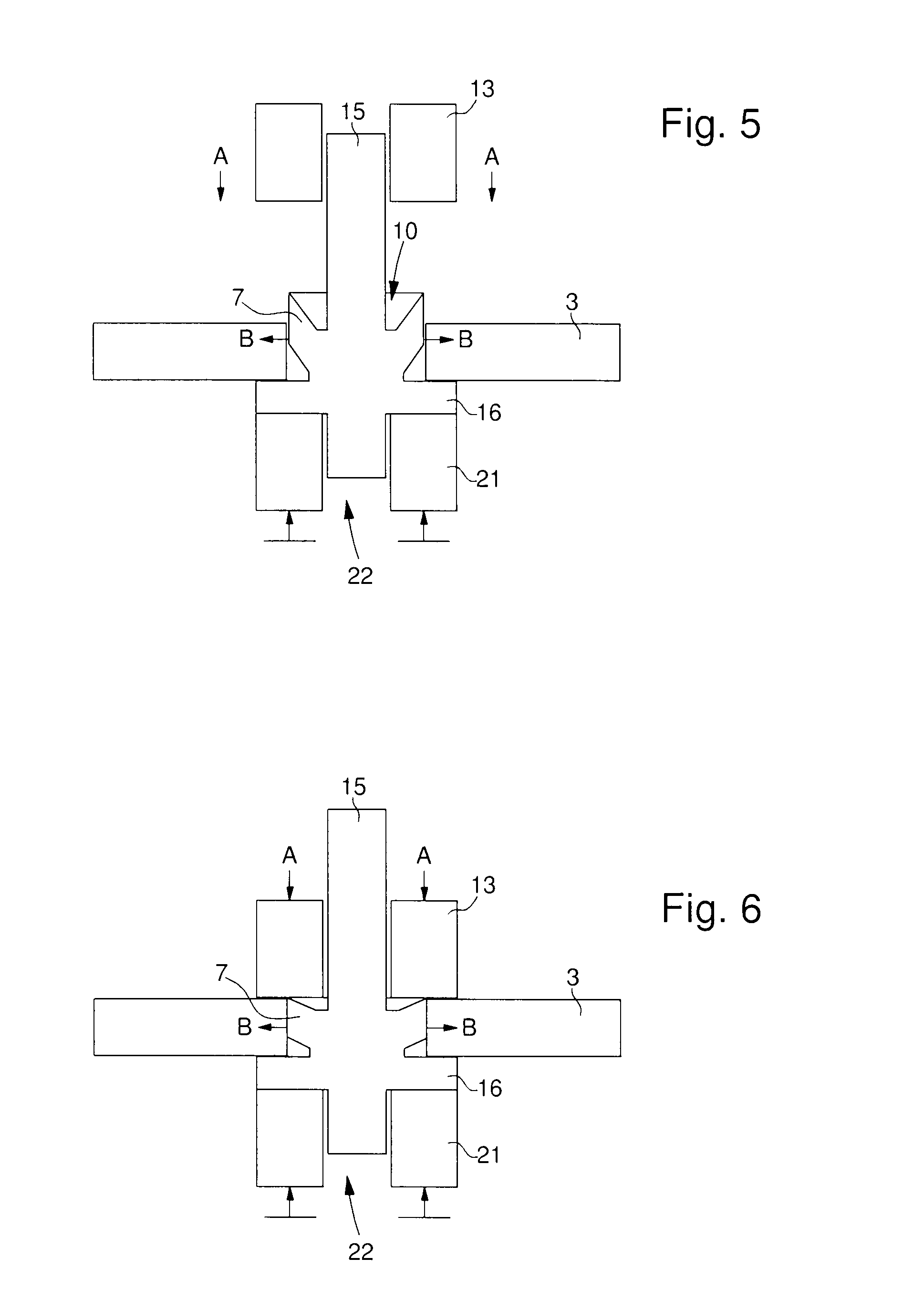
[0064]By way of example, FIGS. 5 to 6 illustrate the method. Thus, FIGS. 5 and 6 show an alternative in which member 15 is substantially different from member 5 in that it has a collar 16. Therefore, the bottom portion of tool 21 is altered and has a through hole 22 the section of which is at least equal to or greater than that of member 15.

[0065]It is therefore clear that member 5 is no longer carried by the radially flared portion 7 but is carried by collar 16 as is, if appropriate, part 3. Further, the deformation of flared portion 7 on the bottom portion thereof is no longer achieved directly using tool 21, but via collar 16, with no loss of advantage to the method. Thus, part 3 is under elastic stress at flared portion 7 and is locked against collar 16 of member 15.

[0066]By way of example, FIGS. 7 to 10 show a third embodiment of the method. Thus, FIGS. 7 to 10 show an alternative wherein the radially flared portion 27, 27′, 27″, 27′″ is substantially different from the flared ...


PUM

PropertyMeasurementUnit
Lengthaaaaaaaaaa
Displacementaaaaaaaaaa
Forceaaaaaaaaaa

Abstract

A method of assembling a member made of a first material in a part made of a second material having no plastic domain, includes forming the part with an aperture, inserting a radially flared portion of the member into the aperture, without any stress, and elastically and plastically deforming the flared portion of the member in the aperture by moving two tools towards each other axially, respectively on the top and bottom parts of the flared portion, so as to exert a radial stress against the wall of the part surrounding the aperture, causing the elastic deformation of the part, to secure the assembly in a manner that is not destructive for said part. The member can be a timepiece.

Description

[0001]This application claims priority from European Patent Application No. 10196585.3 filed Dec. 22, 2010, the entire disclosure of which is incorporated herein by reference.FIELD OF THE INVENTION[0002]The invention relates to the assembly of a part, made of a material having no plastic domain, to a member comprising a different type of material.BACKGROUND OF THE INVENTION[0003]Current assemblies including a silicon-based part are generally secured by bonding. This type of operation requires extremely delicate application which makes it expensive.[0004]EP Patent No. 2 107 433 discloses a first, silicon-based part which is assembled on an intermediate metallic part and the whole assembly is then mounted on a metal arbour. However, the embodiments proposed in this document are unsatisfactory and either cause the silicon-based part to break during assembly, or do not bind the parts sufficiently well to each other.[0005]Indeed, in this document, one end of the intermediate part is fold...

Claims


Application Information

Patent Timeline
IPC IPC(8): B23P11/00
CPCY10T29/49938G04B13/026G04B17/325G04B13/022G04B15/14Y10T29/49581G04D1/0042G04D3/04G04B17/345Y10T29/49934B21K25/00F16B17/006G04B17/06G04B17/066
Inventor VERARDO, MARCOCUSIN, PIERREQUEVAL, ARTHUR
Owner NIVAROX FAR
Why Eureka
Try Eureka