Domestic appliance comprising detent elements and detent counter-elements

a technology of detent elements and counter-elements, which is applied in the direction of centrifuges, manufacturing tools, grain treatment, etc., can solve the problems of high cost of assembly and disassembly of latching devices, and achieve the effect of facilitating assembly and disassembly of housing sections

Inactive Publication Date: 2009-01-06
BSH BOSCH & SIEMENS HAUSGERAETE GMBH
View PDF9 Cites 4 Cited by
  • Summary
  • Abstract
  • Description
  • Claims
  • Application Information

AI Technical Summary

Benefits of technology

[0005]This object is achieved according to the invention in that the locking element has a first end supported on one of the housing sections and a second end interlocking on the latching

Problems solved by technology

However, the disadvantage of this latching device of prior art is th

Method used


Image

  • Domestic appliance comprising detent elements and detent counter-elements
  • Domestic appliance comprising detent elements and detent counter-elements
  • Domestic appliance comprising detent elements and detent counter-elements

Examples


Embodiment Construction

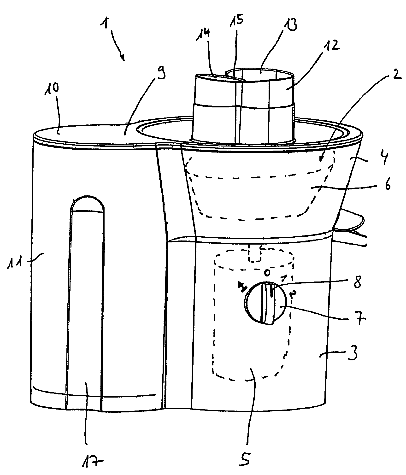
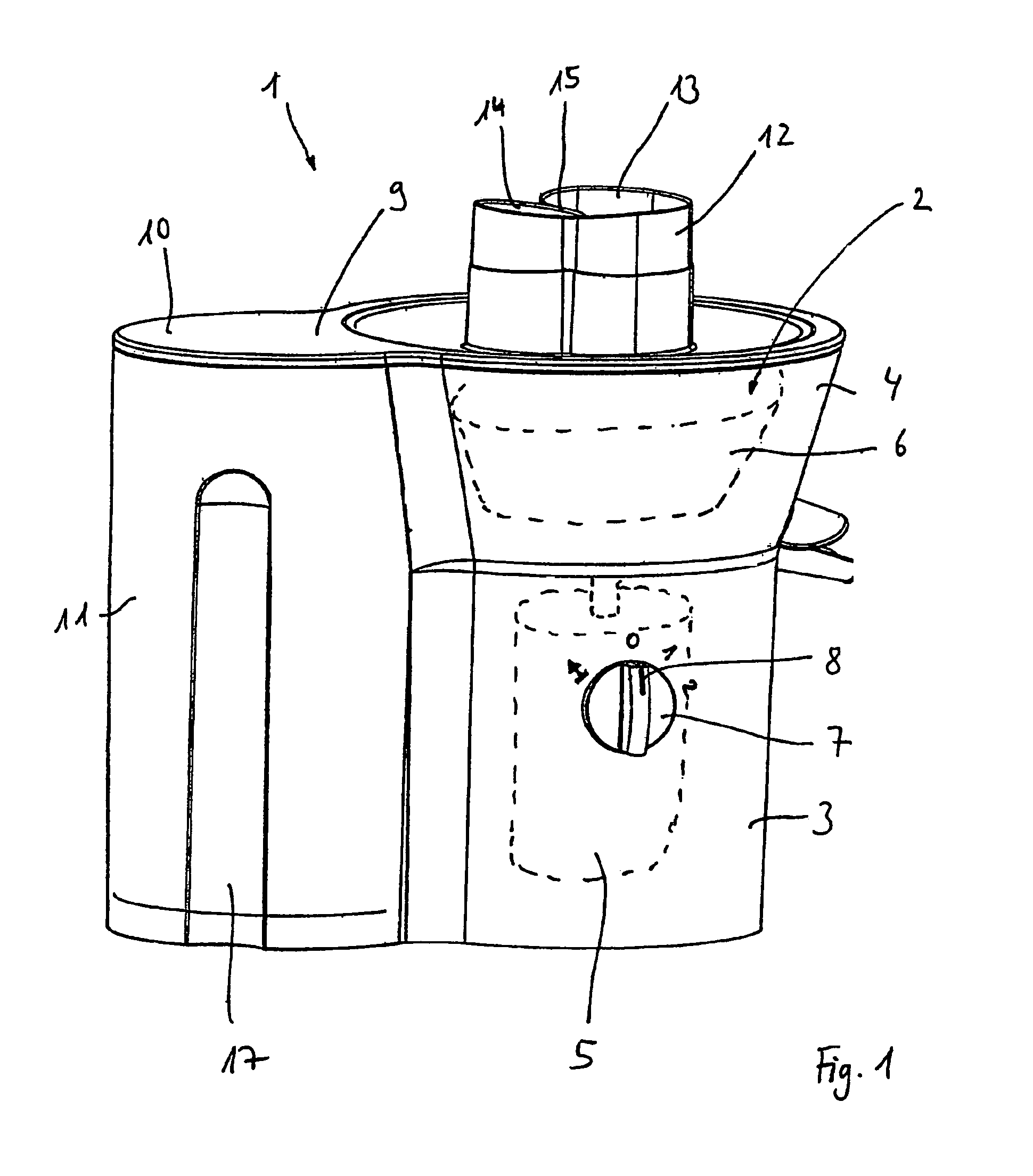
[0023]A juicer 1 shown in FIG. 1 has a housing 2 which comprises an essentially hollow cylindrical lower section 3 and a conically shaped upper section 4.

[0024]A drive motor 5 arranged in lower section 3, for a working tool 6 mounted rotatably in upper section 4, are only shown diagrammatically and in a concealed manner. The electrically operable drive motor 5 can be controlled by a rotatable actuating element 7. Actuating element 7 is designed as a rotary knob and is fitted on a front side wall of hollow cylindrical lower section 3. In the rotary position of actuating element 7 shown, a line marking 8 indicates switch position “0” in which the domestic appliance is put out of operation. In a switching position “I” of actuating element 7, located further to the right in the clockwise direction, juicer 1 is driven at a low speed, and in a switch position “II” of actuating element 7 located even further to the right, juice 1 is driven at a high speed. In a switch position “A” located ...


PUM


Abstract

A domestic appliance comprising at least one housing part with a detent element and at least one second housing part with a detent counter-element. Said elements are designed to interconnect the housing parts and are associated with a locking element, which is used to secure the detent elements, when the locking element is in the locked position, from becoming detached from the detent counter-elements. The aim of the invention is to facilitate the assembly and disassembly of the detent device. To achieve this, the locking element comprises a first end that is supported on one of the housing parts and a second end that engages with the detent element in the locked position. The locking element can thus be pivoted back and forth in a simple manner between a release position and a locked position, facilitating a more rapid, simpler assembly and disassembly.

Description

BACKGROUND OF THE INVENTION[0001]The invention relates to a domestic device with at least a first housing section which has a latching means and at least a second housing section which has a counter-latching means, which latching and counter-latching means are provided for connecting the housing sections and which are assigned a locking element by means of which the latching means is protected from becoming detached from the counter-latching means in a locking position of the locking element.[0002]DE 101 42 508 A1 discloses a latching device for fastening a first body which can be inserted in a second body, in which a first wall of the first body extends essentially at right angles to a second wall of the second body, with a latching projection which is arranged on an inside of the first wall enclosed by the second body, and which can be pushed into a latching opening by a force exerted by a connecting means connected to the first body.[0003]However, the disadvantage of this latchin...

Claims


Application Information

Patent Timeline
IPC IPC(8): A23N1/00F16B5/06
CPCF16B5/0607Y10T292/103
Inventor MAZEJ, STANISLAVOGRIZEK, DARKOSEDOVSEK, ALEKSANDERSEMEJA, UROSZIBRET, IGOR
Owner BSH BOSCH & SIEMENS HAUSGERAETE GMBH
Why Eureka
Try Eureka