Carburetor of an internal combustion engine

a technology of internal combustion engine and carburetor, which is applied in the direction of machines/engines, liquid fuel feeders, separation processes, etc., can solve the problems of large co fluctuations in exhaust gas, and achieve the effect of improving the adjustment effect of the main adjusting screw

Active Publication Date: 2009-01-06
ANDREAS STIHL AG & CO KG
View PDF7 Cites 0 Cited by
  • Summary
  • Abstract
  • Description
  • Claims
  • Application Information

AI Technical Summary

Benefits of technology

[0015]The present invention is based on the recognition that vapor bubbles can form in the fuel system of the carburetor not only when the engine is shut off but also during operation, which can then not be flushed out by actuating the purer prior to the start up process. Such gas bubbles can collect, or can grow after being formed, in regions of the fuel path that are not subjected to a permanent flow-through as a result of operation. In particular in the pump chamber of the accelerator pump gas bubbles result from the evolution of gas as a consequence of vibrations or due to the under pressure that results with each change in load during filling of the accelerator pump. These gas bubbles tend to surge and cause great CO fluctuations in the exhaust gas. Guiding a fuel channel that has fuel flow continuously therethrough during operation through the pump chamber of the accelerator pump subjects the pump chamber to a continuous flushing during operation. Thus, the formation of gas bubbles is avoided. Gas bubbles that nonetheless form are flushed out right at the beginning, before they have achieved a disruptive magnitude. In particular when the throttle is opened, during which the contents of the pump chamber are pressed into the intake channel, a considerable improvement in precision and reproducibility of the fuel / air ratio that is provided can be observed. Running of the engine and emission values are reliably improved.
[0017]Pursuant to a preferred variation, the main nozzle section is divided into two partial channels that are connected in parallel, whereby the main adjusting screw is provided in the first partial channel, and the pump chamber is disposed in the second partial channel without the main adjusting screw. The quantity that flows through the first partial channel can be variably adjusted by means of the main adjusting screw, while the quantity that flows through the second partial channel remains essentially constant. The adjustment effect of the main adjusting screw is improved. At the same time, there is ensured that the pumping and flushing effect of the accelerator pump is not influenced by the position of the main adjusting screw.
[0018]A check valve is expediently provided upstream of the accelerator pump; this check valve is in particular connected directly with the regulating chamber. Upon actuation of the accelerator pump, the check valve closes and ensures that the pump quantity that is provided does not pass back into the regulating chamber, but rather passes entirely into the intake channel. The direct connection with the regulating chamber permits easy installation or removal when the regulating chamber is opened.

Problems solved by technology

These gas bubbles tend to surge and cause great CO fluctuations in the exhaust gas.

Method used


Image

  • Carburetor of an internal combustion engine
  • Carburetor of an internal combustion engine
  • Carburetor of an internal combustion engine

Examples


Embodiment Construction

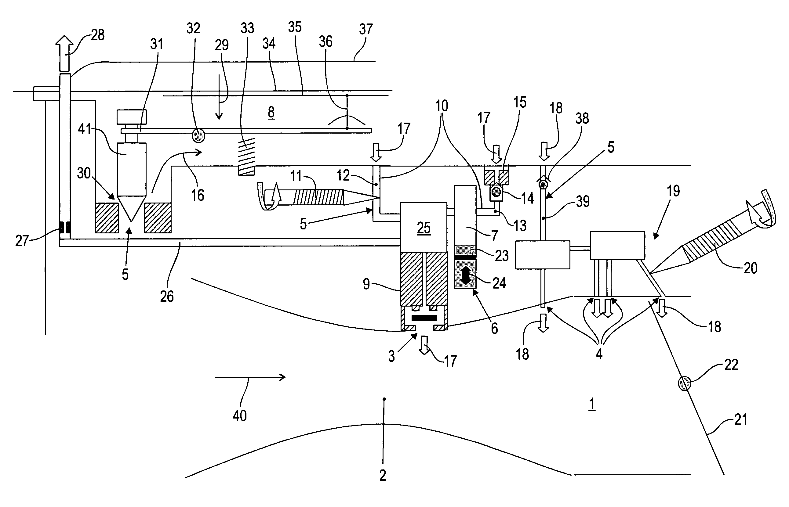
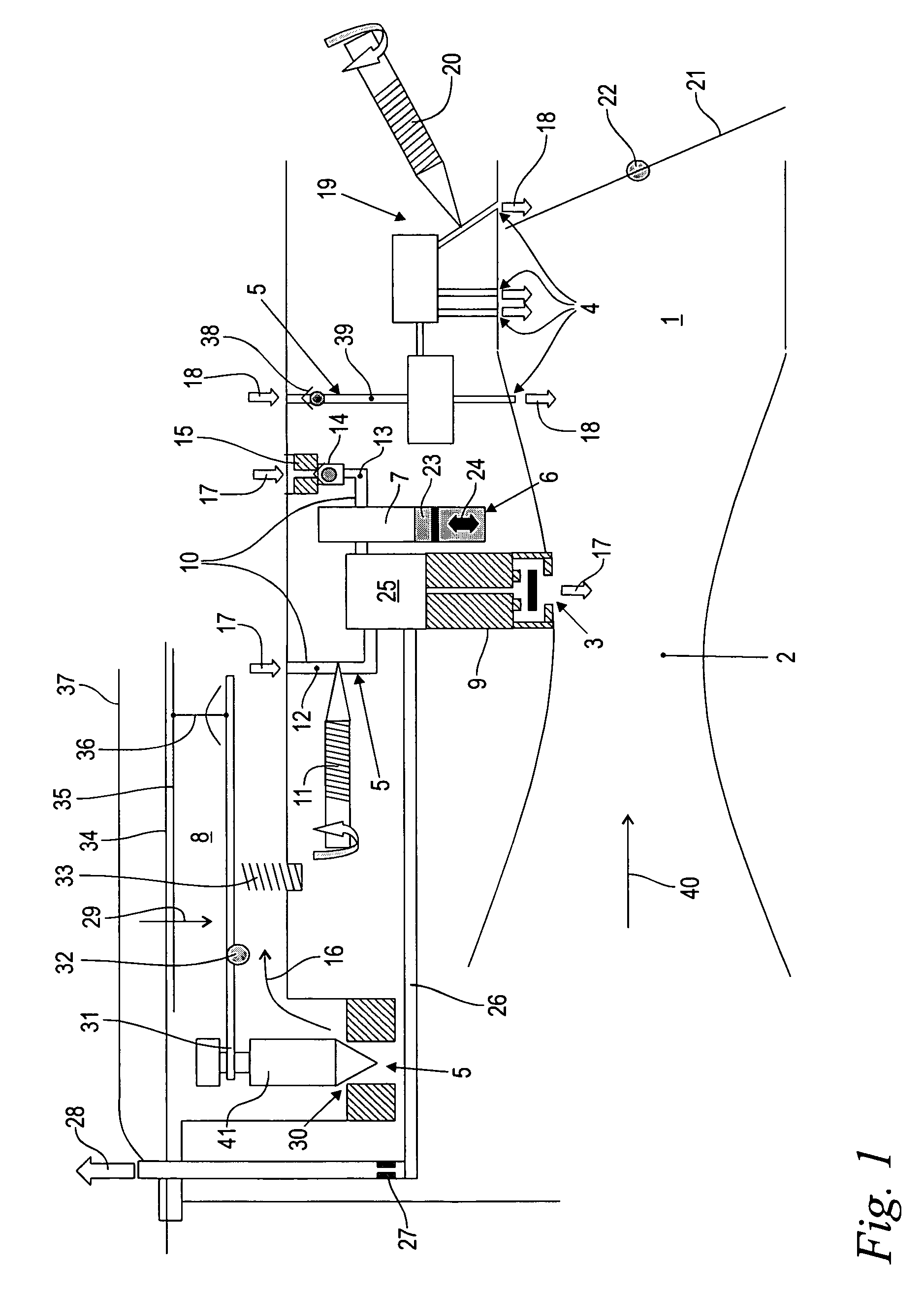
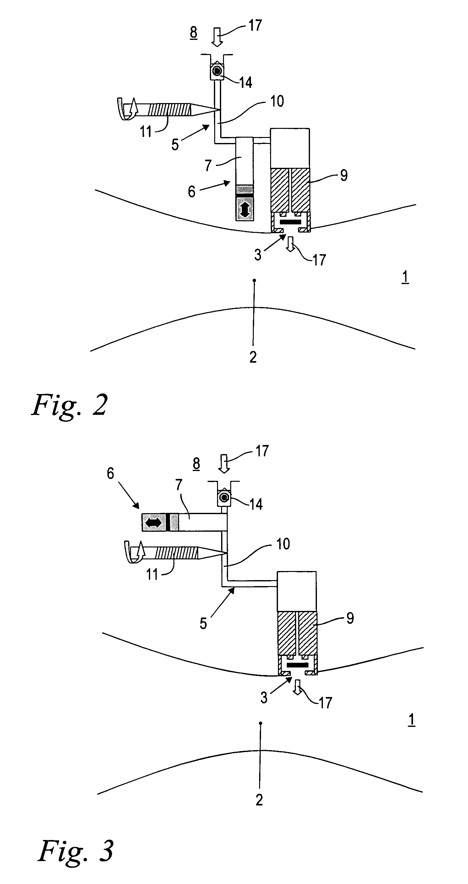
[0020]Referring now to the drawings in detail,FIG. 1 shows a schematically illustrated carburetor, by way of example a diaphragm carburetor, for an internal combustion engine for operating a manually-guided or portable implement. During operation, the non-illustrated internal combustion engine draws in combustion air in the direction of the arrow 40 through an intake channel 1 of the carburetor. Formed into the intake channel 1 is a venture section 2 that in a rounded manner narrows the flow cross-section. A main nozzle arrangement 9 having a fuel opening 3 is provided approximately at the narrowest cross-section of the venture section 2. Fuel is drawn into the intake channel 1 through the fuel opening 3 in the direction of the arrow 17 due to the under pressure that exists in the venture section 2 as a result of operation. To control the power of the internal combustion engine, provided downstream of the venture section 2 is a throttle or butterfly valve 21, which is pivotable abou...


PUM

PropertyMeasurementUnit
temperaturesaaaaaaaaaa
speedaaaaaaaaaa
combustionaaaaaaaaaa

Abstract

A carburetor of an internal combustion engine for operating a manually-guided implement, including an intake channel having a venturi section for combustion air, a fuel channel that opens into the intake channel via a fuel opening, and an accelerator pump that is in flow-conducting communication with the fuel opening. During operation of the carburetor, the fuel channel is adapted to have fuel flow continuously therethrough. The fuel channel is guided through a pump chamber of the accelerator pump.

Description

[0001]The instant application should be granted the priority date of Aug. 1, 2005 the filing date of the corresponding German patent application 10 2005 036 091.2.BACKGROUND OF THE INVENTION[0002]The present invention relates to a carburetor of an internal combustion engine for operating a manually-guided implement such as a chain saw, a brush cutter, or the like.[0003]Manually-guided implements such as chain saws, brushcutters, or the like are subjected during operation to changing environmental conditions under which the internal combustion engine, as a drive engine, must operate cleanly at various temperatures, vibration loads, or the like. In addition to a clean running at uniform load and speed, it is also desirable to have a good operating characteristic during start up and during sudden supplies of gas, i.e. during accelerations.[0004]To supply the internal combustion engine with a fuel / air mixture, a carburetor is provided with which a stream of combustion air is drawn in th...

Claims


Application Information

Patent Timeline
Patent Type & Authority Patents(United States)
IPC IPC(8): F02M7/08
CPCF02M7/08Y10S261/81
Inventor PAA, ANDREAS
Owner ANDREAS STIHL AG & CO KG
Why Eureka
Try Eureka