Gate retention mechanism for a conveyor assembly

a technology of conveyor assembly and retention mechanism, which is applied in the direction of rope railway, transportation and packaging, and ways, can solve the problems of weak switching mechanism, inability to support the weight of goods, and current use of switching mechanism, and achieve the effect of strong connection points

Active Publication Date: 2011-09-06
INDAL DESIGN FABTION & INSTALLATION
View PDF25 Cites 0 Cited by
  • Summary
  • Abstract
  • Description
  • Claims
  • Application Information

AI Technical Summary

Benefits of technology

[0007]To this end, an improved rail section and rail switch for a conveyor, and a method of manufacturing and assembling same, is provided. The rail section of the present invention comprises a connecting mechanism for connecting to the switch mounting and gate operating mechanism. Specifically, the connecting mechanism includes an aperture in the rail section through which a connecting portion of the switch mounting is inserted. Once the connecting portion of the switch mounting is inserted, a double weld can be used to hold the switch mounting in place. To accomplish this, one weld is placed on each face of the rail section at the point where the rail section contacts the switch mounting. The gate operating mechanism is connected to the rail section in much the same way. An aperture is provided, and a connecting portion of the gate operating mechanism is inserted through the aperture. A double weld may then be used to hold the gate operating mechanism in place. In this way, the rail section of the present invention provides stronger connection points that can withstand heavier loads.
[0008]The gate receptor of the present invention is also reinforced to withstand heavier loads. Specifically, a thickness and shape of the rail section is provided having increased strength. Furthermore, a rail section of the present invention may be CNC (Computer Numerically Controlled) cut from a single piece of material in order to add strength and improve the precision and reproducibility of components for a more precise fit.

Problems solved by technology

Switching mechanisms currently being used have been found to be structurally weak at certain points so that they are unable to support the weight of the goods as the trolleys travel across the rail sections.
Specifically, these switching mechanisms have been found to be weak at the points where the rail section connects to the switch mounting and gate operating mechanism, and also at the gate receptor portion of the rail section.
These structural weaknesses in the switching mechanism significantly reduce the structural load capabilities of the rail and are prone to breakage.
Not only does this cost time and expense for the repair and / or replacement of components, but this is also a serious safety hazard because falling product from a broken switch could injure employees or other people standing in the vicinity.
Another problem with switching mechanisms currently in use is that replacement parts may not fit well.
This can lead to inaccuracies and imprecision which can cause parts not to fit properly, which, in turn, can lead to loose parts, wobble in the device, and other concerns.

Method used


Image

  • Gate retention mechanism for a conveyor assembly
  • Gate retention mechanism for a conveyor assembly
  • Gate retention mechanism for a conveyor assembly

Examples


Embodiment Construction

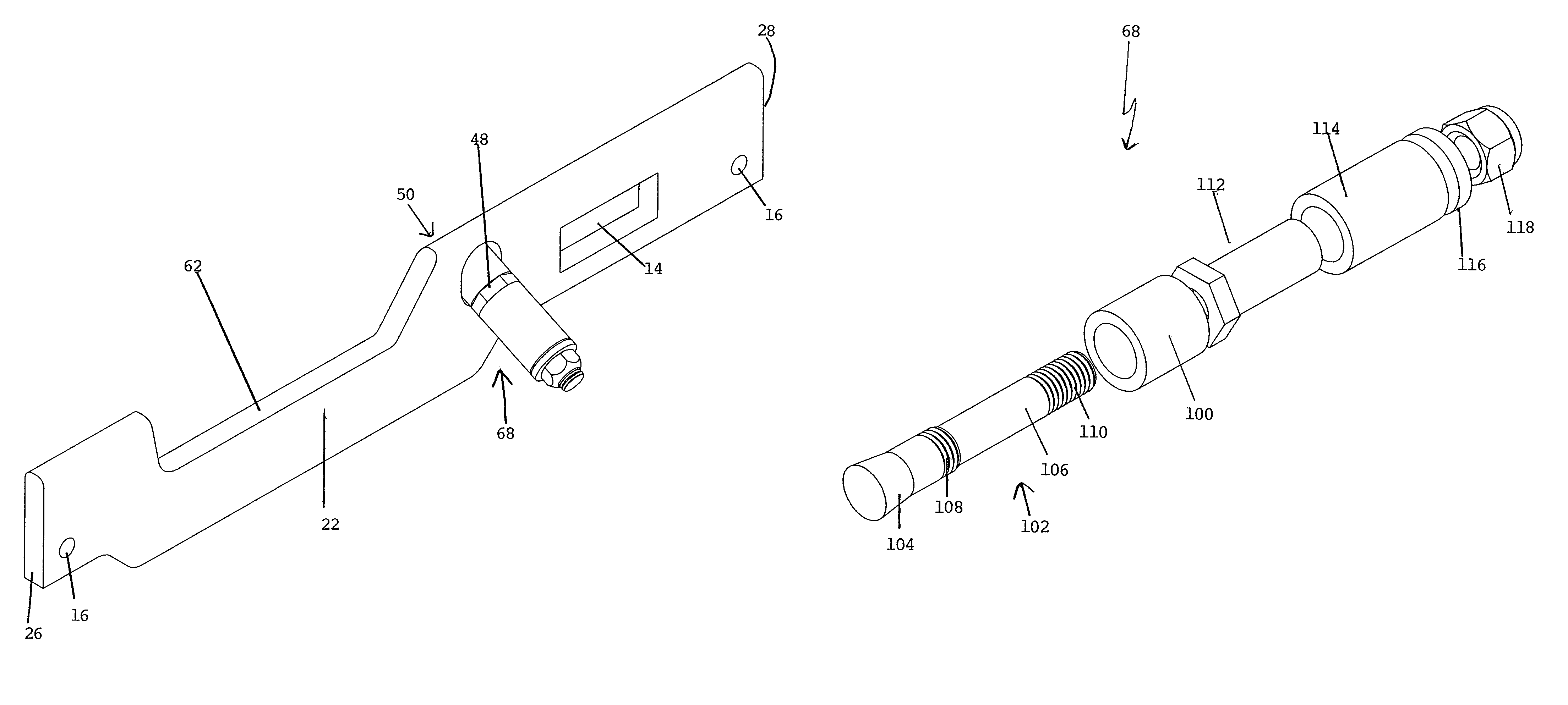
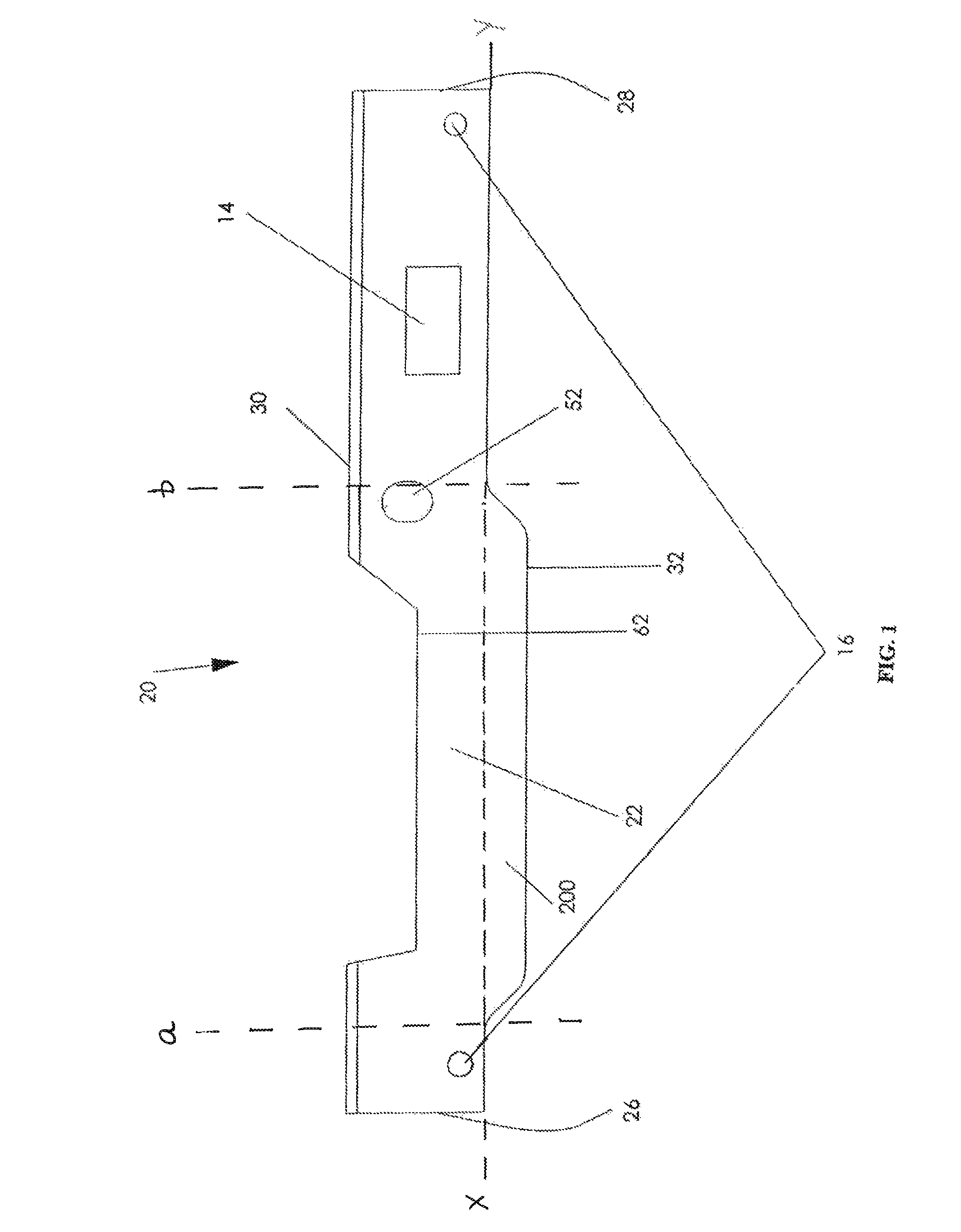
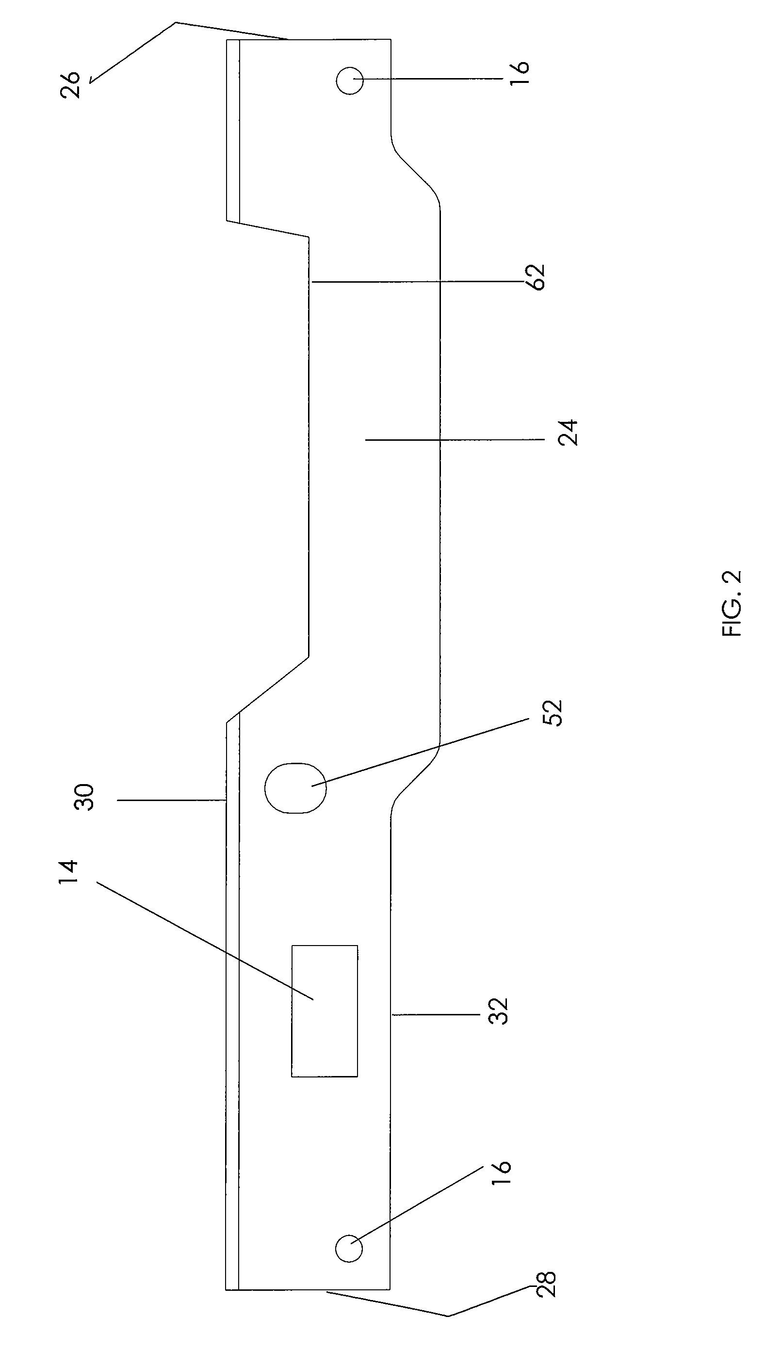
[0039]While the disclosure herein is particularly described with regard to overhead trolley conveyors used in food processing or manufacturing, it will be understood and apparent to those of skill in the art that the present invention has other applications where switching mechanisms are used at points where rails or tracks intersect, in order to direct the objects moving along a track system.

[0040]As can be seen in the Figures, the rail section 20 of the present invention generally comprises a first end 26, second end 28, first face 22, second face 24, a top surface 30 and a bottom surface 32. The rail section of the preferred embodiment also includes holes or apertures for connecting the rail section to other rails in the rail system and to the other components of a switch mechanism 60. The rail section 20 shown in FIGS. 1 and 2 includes two rail connecting holes 16 which are used to connect the rail to the other adjacent rails of the system (not shown) which make up the track of ...


PUM

PropertyMeasurementUnit
resist movementaaaaaaaaaa
movementaaaaaaaaaa
weightaaaaaaaaaa

Abstract

A rail section for use in a rail switch and method for assembling same are provided. The rail section is connected to a switch mounting by inserting a portion of the switch mounting through an aperture provided in the rail section and then applying a double weld. Similarly, a gate operating mechanism is connected to the rail section by inserting a portion of the gate operating mechanism through an aperture provided in the rail section and then applying a double weld. A receptor portion of the rail section that is reinforced to withstand a greater load is also provided. A plurality of gate retention mechanisms are also disclosed.

Description

FIELD OF INVENTION[0001]The rail section, switch mechanism, and method disclosed relate generally to switching mechanisms used in directing the movement of objects in various directions along a rail or track system, and more particularly to overhead rails and switching mechanisms for conveyors.BACKGROUND[0002]It is known to use overhead rail systems along which trolleys travel in order to move goods during processing or manufacture. The overhead rail systems are designed and installed so that goods may be suspended from the trolleys and then moved in different directions along the rail system to transfer the goods from a first location to a second location. For example, such overhead rail systems are commonly used in meat packing plants in which meat is hung from the trolley. Some overhead rail systems use a rail switching mechanism at points in the track or rail where rails traveling in different directions intersect. The switching mechanism operates to control and direct the movem...

Claims


Application Information

Patent Timeline
Patent Type & Authority Patents(United States)
IPC IPC(8): B61B3/00
CPCB65G9/008Y10T29/49826Y10T83/0524
Inventor JAGER, TODDBEERS, CARLTON
Owner INDAL DESIGN FABTION & INSTALLATION
Why Eureka
Try Eureka