
Mask making method, mask making device, and mask drawing device

a mask and drawing technology, applied in the field of mask making methods, mask making devices, and mask drawing devices, can solve the problems of difficult to enhance the accuracy of such movement, difficult to provide or prepare a number of such systems, and the price of mask writing, so as to reduce the time required for lithography the whole, increase the accuracy of movement when forming the first pattern, and reduce the time. the effect of lithography

Inactive Publication Date: 2009-01-06
FOUND FOR ADVANCEMENT OF INT SCI +1
View PDF16 Cites 0 Cited by
  • Summary
  • Abstract
  • Description
  • Claims
  • Application Information

AI Technical Summary

Benefits of technology

[0008]On the other hand, with respect to the exposure technique using the proximity mask, it has been considered that since the area of the mask is small, the mask can be manufactured in a relatively short time and therefore the cost of the mask can be reduced. However, since the line width of a pattern is required to have a small value of about 0.07 μm or less that is substantially equal to that of an actual chip, when the mask is written by the use of the EB lithography system, it has been difficult to achieve a high writing accuracy.
[0013]It is an object of this invention to provide a mask writing method and a mask writing system that can manufacture a mask in a short time with a high accuracy, thereby solving the conventional problems as described above.
[0014]It is another object of this invention to provide a system that can remarkably improve the stitching accuracy and that can delineate a mask at a high speed.
[0017]According to each of these methods, the mask is not directly written by the use of the first pattern formed by the light control elements arranged in the two-dimensional array, but is written by the use of the reduced second pattern or the further reduced third pattern. Therefore, the size of the first pattern can be set large. As a result, the moving accuracy when forming the first pattern can be increased (i.e. with a low accuracy) even by approximately one figure. Therefore, it can be moved in an instant so that a time required for lithography the whole can be shortened.

Problems solved by technology

What has been widely pointed out in recent years as a problem in the mask writing is a price rise in mask.
Since the EB lithography system is an extremely expensive system costing several hundred million yen to several thousand million yen or more per system, it is actually difficult to provide or prepare a number of such systems.
However, there has been a problem that it is difficult to enhance the accuracy of such movement and therefore not possible to cope with the miniaturization.
However, since the line width of a pattern is required to have a small value of about 0.07 μm or less that is substantially equal to that of an actual chip, when the mask is written by the use of the EB lithography system, it has been difficult to achieve a high writing accuracy.
It is almost impossible to move a stage in an instant with this accuracy.
Therefore, with respect to the proximity mask, it has been a problem that there is no mask lithography system that can perform lithography at a high speed.

Method used


Image

  • Mask making method, mask making device, and mask drawing device
  • Mask making method, mask making device, and mask drawing device
  • Mask making method, mask making device, and mask drawing device

Examples


first embodiment

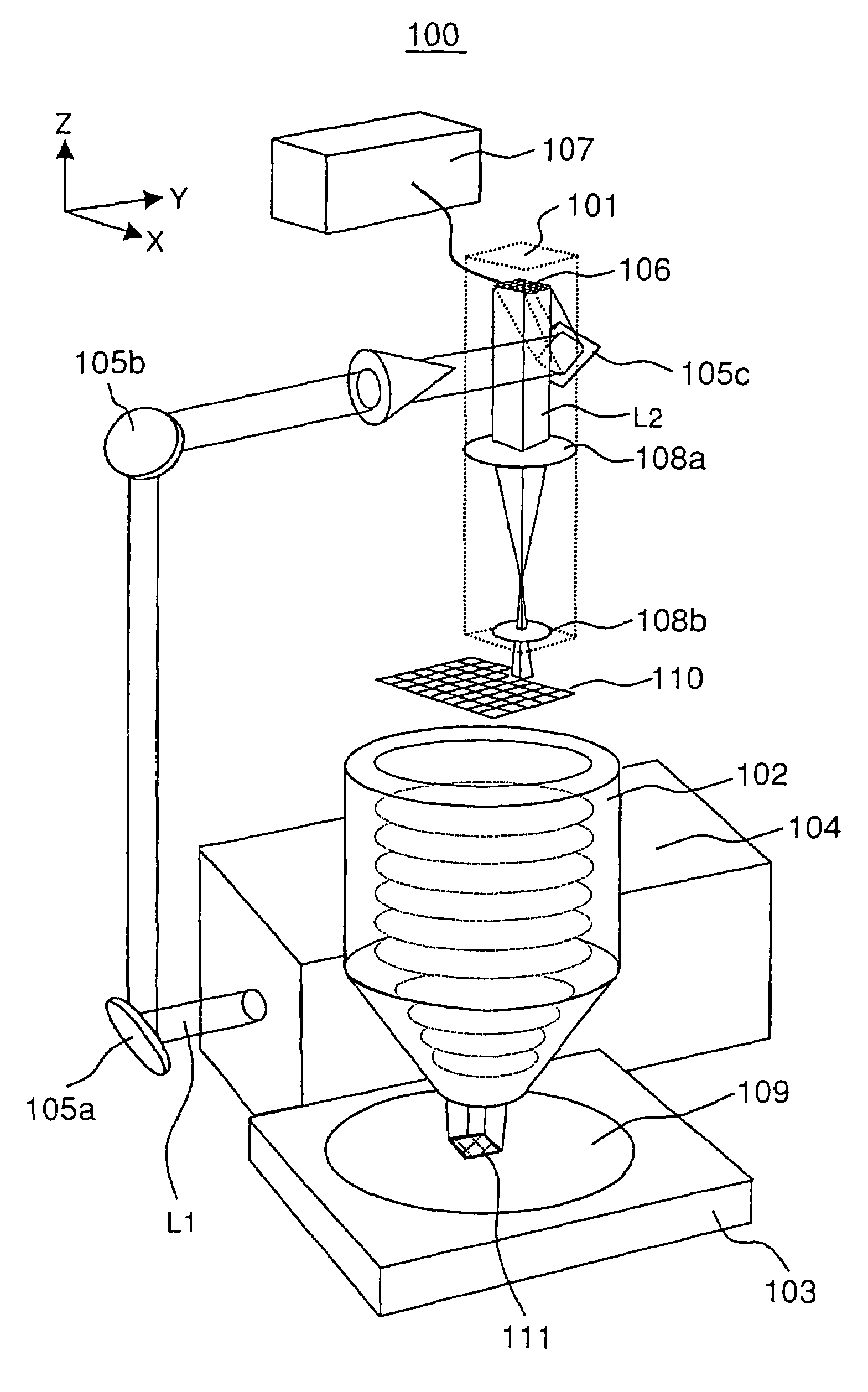
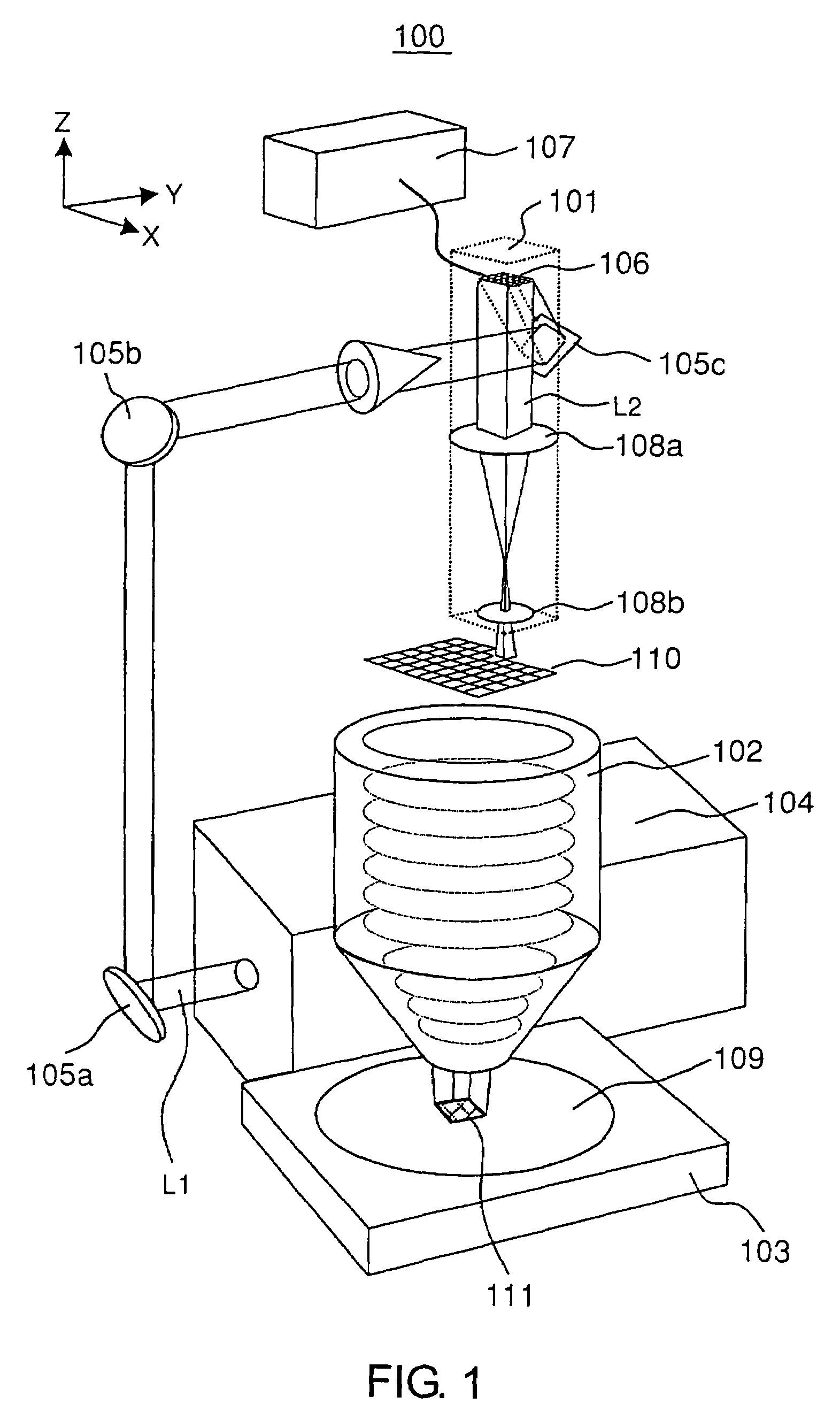
[0031]FIG. 1 is a structural diagram of a mask writing system 100 according to this invention. The mask writing system 100 comprises an enlarged-pattern generating portion 101 having a two-dimensional array micromirror 106 that can form an optional pattern, a reduction-projection optical system 102, a stage 103 having a mask substrate 109 placed thereon, and an ultraviolet laser oscillator 104 for generating laser light L1 in the ultraviolet wavelength region to which a resist applied to the mask substrate 109 is sensitive.

[0032]The laser light L1 extracted from the ultraviolet laser oscillator 104 is reflected by mirrors 105a and 105b and is projected onto a mirror 105c in the enlarged-pattern generating portion 101 so as to be irradiated onto the two-dimensional array micromirror 106.

[0033]In the two-dimensional array micromirror 106, micromirrors are individually controlled by data given from a mask pattern data output device 107 so that the micromirrors are controlled to form a ...

second embodiment

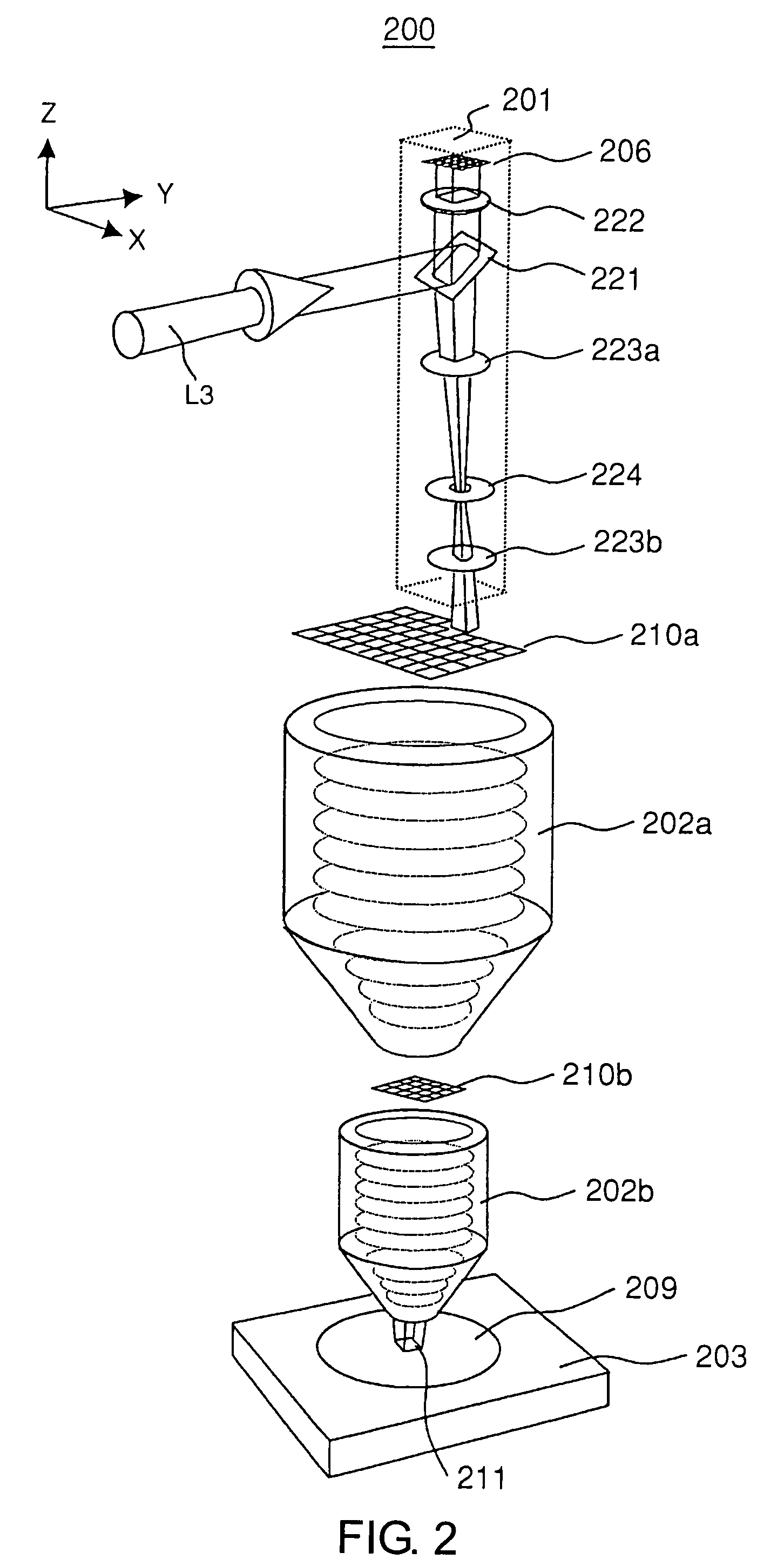
[0041]FIG. 2 is a structural diagram of a mask writing system 200 according to this invention. As compared with the mask writing system 100 shown in FIG. 1, this embodiment differs in two points which will be described hereinbelow. The other basic structure is the same. Although use is made of an ultraviolet laser oscillator for generating laser light in the ultraviolet region and a pattern data output device, they are omitted in FIG. 2. The different points are a control system for ultraviolet laser light in an enlarged-pattern generating portion 201 and a structure of a reduction-projection optical system.

[0042]Laser light L3 is incident upon a beam splitter 221 in the enlarged-pattern generating portion 201 and is reflected upward to pass through a wavelength plate 222 so as to be incident upon a two-dimensional array micromirror 206. Laser light reflected by micromirrors corresponding to a pattern forming part of an intended mask lithography pattern in the two-dimensional array ...

third embodiment

[0046]FIG. 3 is a structural diagram of a mask writing system 300 according to this invention. In the mask writing system 300, a two-dimensional array self-light-emitting device 306 is used as light control elements arranged in a two-dimensional array, which forms this invention. In the two-dimensional array self-light-emitting device 306, only those elements corresponding to a pattern of part of an intended mask lithography pattern are caused to emit light. Then, a light-emission pattern thereof is reduced through a first reduction-projection optical system 302a and a second enlarged pattern 310b is reduced through a second reduction-projection optical system 302b so that a lithography pattern 311 is formed on a mask substrate 309 on a stage 303. The two-dimensional array self-light-emitting device 306 can be scanned in X- and Y-directions in the figure, thereby constituting a first enlarged pattern 310a formed with the entire lithography pattern.

[0047]As the two-dimensional array ...


PUM

PropertyMeasurementUnit
widthaaaaaaaaaa
widthaaaaaaaaaa
widthaaaaaaaaaa

Abstract

Laser light in a pattern reflected by a two-dimensional array micromirror 106 that is controlled on the basis of mask data of a mask pattern data output device 107 forms an enlarged pattern 110. This enlarged pattern is projected in a reduced manner onto a mask substrate 109 through a reduction-projection optical system 102, thereby forming a lithography pattern 111. Since a large number of patterns are written in an instant by the two-dimensional array micromirror 106, a time required for lithography the entire mask pattern is extremely shortened as compared with a conventional one. As a result, the mask cost can be largely reduced.

Description

[0001]This application is a National Stage application of PCT / JP2004 / 000740 filed Jan. 28, 2004, which claims priority from Japanese patent applications JP 2003-018960, filed Jan. 28, 2003 and JP 2003-078951, filed Mar. 20, 2003. The entire contents of each of the aforementioned applications are incorporated herein by reference.TECHNICAL FIELD[0002]This invention relates to a method of writing a mask for use in an exposure process at the time of manufacturing a semiconductor integrated circuit and to a system for writing the mask. An objective mask according to this invention may be, for example, either a photomask for photolithography that uses ultraviolet-ray radiation or X-ray radiation as an exposure light source or an electron-beam proximity mask.BACKGROUND ART[0003]Generally, in order to write a mask (may be called a reticle also) that is used in manufacturing a semiconductor integrated circuit, it is necessary to provide, on the surface of a quartz plate or the like which wil...

Claims


Application Information

Patent Timeline
Patent Type & Authority Patents(United States)
IPC IPC(8): G03B27/54G03B27/52G03F7/20
CPCG03F7/70291G03F7/70283
Inventor OHMI, TADAHIROSUGAWA, SHIGETOSHITAKEHISA, KIWAMU
Owner FOUND FOR ADVANCEMENT OF INT SCI
Learn More