Versatile compact transmitter for generation of advanced modulation formats

a compact transmitter and modulation format technology, applied in the field of signal transmission, can solve the problem that direct modulated lasers (dml) typically reach 5 km

Inactive Publication Date: 2009-01-06
II VI DELAWARE INC
View PDF86 Cites 28 Cited by
  • Summary
  • Abstract
  • Description
  • Claims
  • Application Information

AI Technical Summary

Problems solved by technology

On the other hand, directly modulated lasers (DML) typically reach <5 km because their inherent time-dependent chirp causes severe distortion of the signal after this distance.

Method used


Image

  • Versatile compact transmitter for generation of advanced modulation formats
  • Versatile compact transmitter for generation of advanced modulation formats
  • Versatile compact transmitter for generation of advanced modulation formats

Examples


Embodiment Construction

The DPSK Format

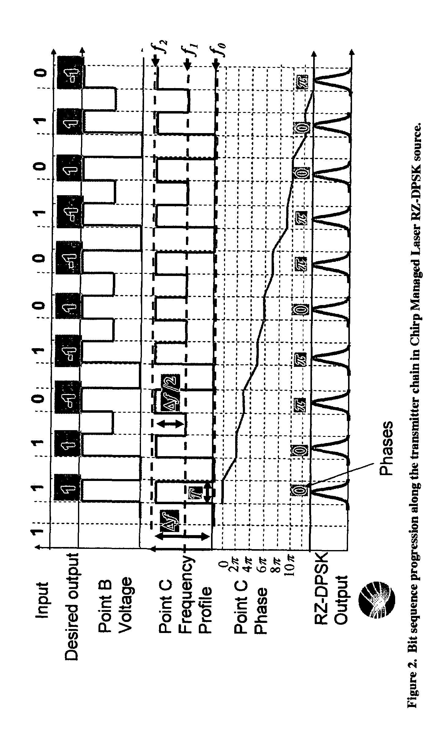
[0031]In the DPSK format, an input digital electrical signal representing 1s and 0s is converted to an optical signal where the information is encoded in the phase of a continuous-wave (CW), constant-amplitude signal. In this DPSK format, the modulation rule is that, given an input random digital sequence of 1s and 0s bits, the phase of the CW signal is changed by π for every occurrence of a 0 bit while the phase is unchanged for the occurrence of a 1 bit. As an example, consider the digital sequence and the resulting DPSK phase of the bits shown below in Table 1:

[0032]

TABLE 1(a) Digital signal:1 1 1 0 1 0 0 1 0 1 0 0 0 1 1 0 1 0 1 1 0 1 1 . . .(b) Phase of bits:0 0 ππ 0 ππ 0 0 π 0 πππ 0 0 . . .(c) Amplitude of bits:1 1 −1 −1 1 −1 −1 1 1 −1 1 −1 −1 −1 . . .(d) Intensity of bits:1 1 1 1 1 1 1 1 1 1 1 1 1 1 1(1)

Here the amplitude refers to the optical electric field of the bit, which carries phase information, whereas intensity refers to the optical power in the bits, w...


PUM


Abstract

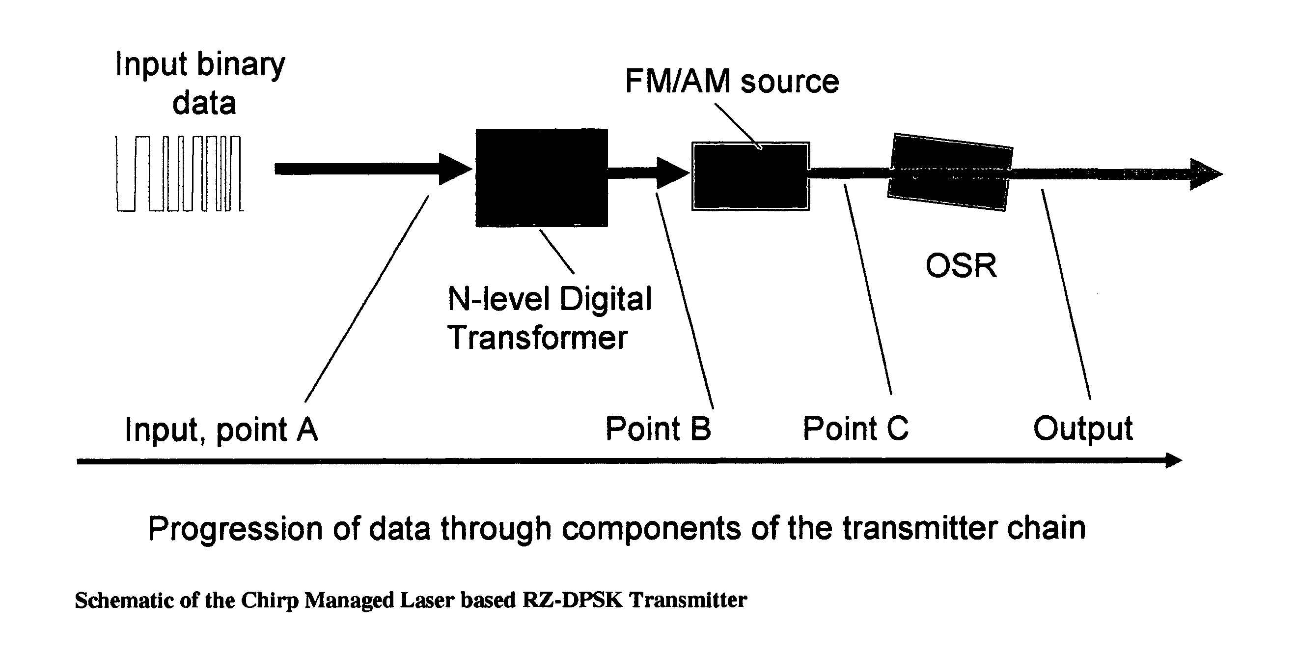
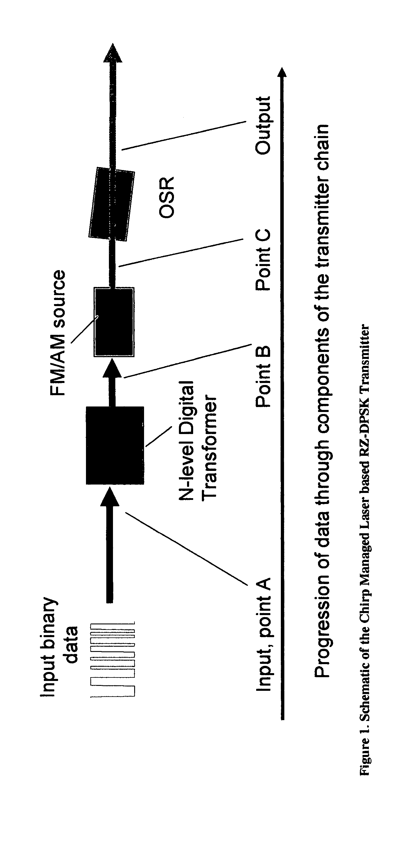
A system for generating a return-to-zero differentially-phase-shift-keyed (RZ-DPSK) optical signal comprising:a driver comprising an N-level digital multilevel transformer (DMT) configured to receive a two level digital electrical signal representing 1s and 0s and output a N-level electrical signal, wherein N>2;an FM source configured to receive the N-level electrical signal output by the driver and generate an optical frequency modulated signal; andan optical spectrum reshaper (OSR) configured to receive the optical frequency modulated signal output by the FM source and generate the desired RZ-DPSK optical signal. A method for generating a return-to-zero differentially-phase-shift-keyed (RZ-DPSK) optical signal, the method comprising:(1) receiving a two level digital electrical signal representing 1s and 0s and outputting a N-level electrical signal, wherein N>2;(2) receiving the N-level electrical signal output and generating an optical frequency modulated signal; and(3) receiving the optical frequency modulated signal and generating the desired RZ-DPSK optical signal.

Description

REFERENCE TO PENDING PRIOR PATENT APPLICATIONS[0001]This patent application:[0002](i) is a continuation-in-part of pending prior U.S. patent application Ser. No. 11 / 272,100, filed Nov. 8, 2005 by Daniel Mahgerefteh et al. for POWER SOURCE FOR A DISPERSION COMPENSATION FIBER OPTIC SYSTEM;[0003](ii) is a continuation-in-part of pending prior U.S. patent application Ser. No. 10 / 308,522, filed Dec. 3, 2002 by Daniel Mahgerefteh et al. for HIGH-SPEED TRANSMISSION SYSTEM COMPRISING A COUPLED MULTI-CAVITY OPTICAL DISCRIMINATOR;[0004](iii) is a continuation-in-part of pending prior U.S. patent application Ser. No. 11 / 441,944, filed May 26, 2006 by Daniel Mahgerefteh et al. for FLAT DISPERSION FREQUENCY DISCRIMINATOR (FDFD);[0005](iv) is a continuation-in-part of pending prior U.S. patent application Ser. No. 11 / 068,032, filed Feb. 28, 2005 by Daniel Mahgerefteh et al. for OPTICAL SYSTEM COMPRISING AN FM SOURCE AND A SPECTRAL RESHAPING ELEMENT;[0006](v) is a continuation-in-part of pending p...

Claims


Application Information

Patent Timeline
Patent Type & Authority Patents(United States)
IPC IPC(8): H04B10/04H04B10/155
CPCH04B10/505H04B10/516H04B10/5162H04B10/5561H04B2210/517
Inventor MAHGEREFTEH, DANIELZHENG, XUEYANMATSUI, YASUHIROTAYEBATI, PARVIZ
Owner II VI DELAWARE INC
Why Eureka
Try Eureka